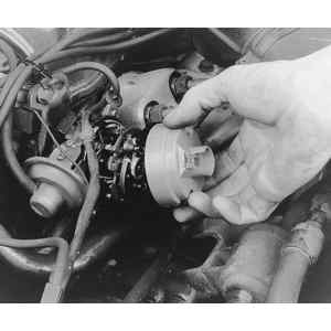
| Fig. 1: View of the air gap measurement on electronic
distributors
|
| Fig. 2: Exploded view of the 1979 electronic distributor
|
| Fig. 3: Exploded view of the 1980–84 electronic
distributor
|
| Fig. 4: Exploded view of the 1986 electronic distributor
|
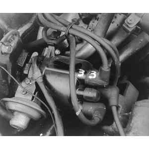
| Fig. 5: Before removing the distributor cap, label the
spark plug wires in relation to their position and cylinder number
|
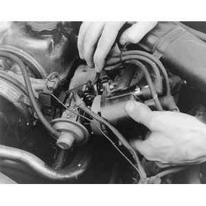
| Fig. 6: Loosen the distributor cap hold-down screws .
. .
|
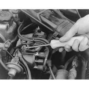
| Fig. 7: . . . and then pull the distributor cap off,
taking care not to upset the firing order — if a new cap
is being installed, remove and replace the ignition wires one at a time
to avoid confusion
|
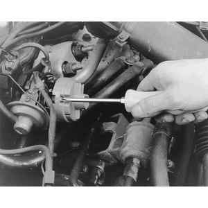
| Fig. 8: Once the cap is removed, loosen the rotor retaining
screws . . .
|
| Fig. 9: . . . and remove the rotor from the distributor
shaft — inspect the rotor and distributor cap contacts
for pitting, burning & wear; replace as necessary
|
Used for the first time on the 1979 models, this system replaces the points and condenser in the distributor. It is almost maintenance free. The most commonly replaced parts are the rotor and cap, which are still routine maintenance items. Other items, such as the pick-up coil and signal rotor, are replaced when they fail. An air gap adjustment is possible only on the 1979 models. Adjustments are not possible on later models.