| Fig. 1: Check the cylinder block deck for warpage by
running a straightedge along both sides, both ends and diagonally as shown.
Use a feeler gauge along the length of the straightedge. Maximum allowable
warpage is 0.003 inches within 6 inches of the deck surface
|
| Fig. 2: Rocker shaft/cylinder head bolt torque sequence
for the 1,586cc, 1,796cc and 1,970cc engines
|
NOTE: The engine must be cold before proceeding.
CAUTION
When draining engine coolant, keep in mind that cats and dogs are attracted
to ethylene glycol antifreeze and could drink any that is left in an uncovered
container or in puddles on the ground. This will prove fatal in sufficient
quantity. Always drain coolant into a sealable container. Coolant should
be reused unless it is contaminated or is several years old.
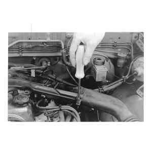
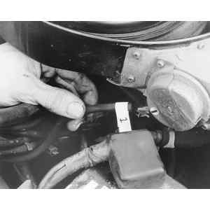
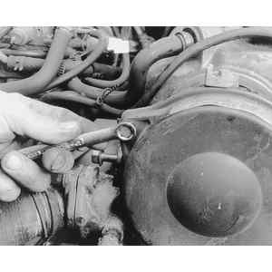
| Fig. 3: After removing the air cleaner lid and filter,
loosen the air injection hose clamps . . .
|
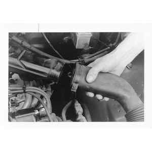
| Fig. 4: . . . and pull the hoses free from the air cleaner
|
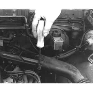
| Fig. 5: Label and remove all vacuum hoses connected to
the air cleaner . . .
|
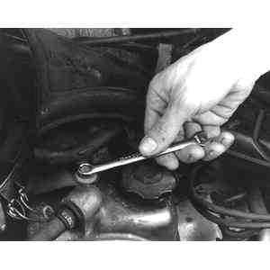
| Fig. 6: . . . then loosen and remove the air cleaner-to-valve
cover bolts
|
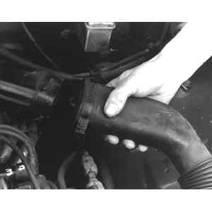
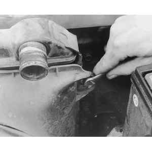
| Fig. 7: Loosen the fresh air hose clamp . . .
|
| Fig. 8: . . . and remove the fresh air hose
|
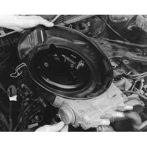
| Fig. 9: Loosen and remove the air cleaner housing-to-carburetor
nuts . . .
|
| Fig. 10: . . . then lift off the air cleaner
|
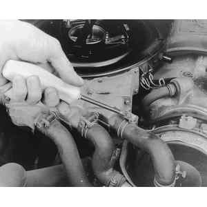
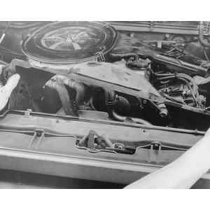
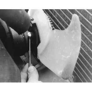
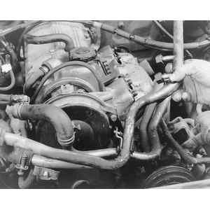
| Fig. 11: Drain the coolant and disconnect the radiator
hoses from the radiator, then loosen and remove the fan shroud attaching
bolts and radiator bolts . . .
|
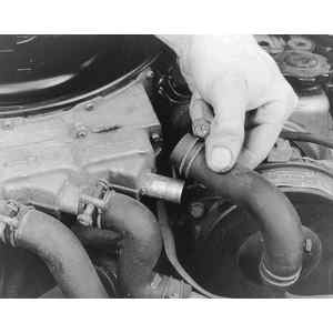
| Fig. 12: . . . and remove the fan shroud and radiator
|
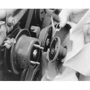
| Fig. 13: Loosen the fan attaching nuts . . .
|
| Fig. 14: . . . and remove the fan
|
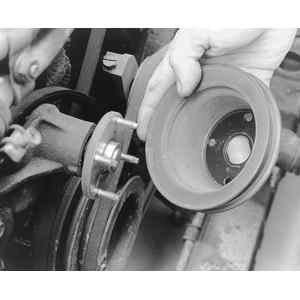
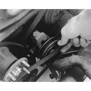
| Fig. 15: After the alternator drive belt has been removed,
take off the fan pulley . . .
|
| Fig. 16: . . . and remove any additional accessory drive
belts
|
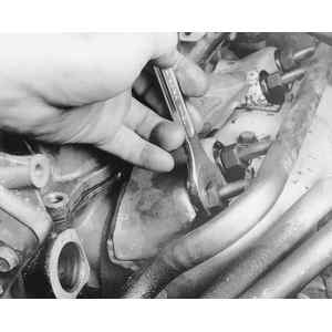
| Fig. 17: After removing the distributor, loosen the air
injection manifold nuts at the top . . .
|
| Fig. 18: . . . as well as from the bottom of the exhaust
manifold, . . .
|
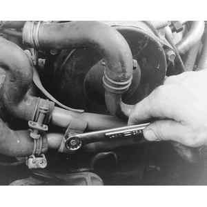
| Fig. 19: . . . then loosen any clamps securing the air
pipes . . .
|
| Fig. 20: . . . and remove the air pipes
|
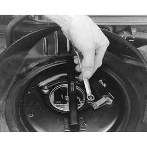
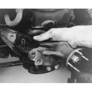
| Fig. 21: To gain access to the front cover, remove the
fan pulley bracket, . . .
|
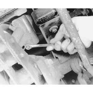
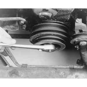
| Fig. 22: . . . then loosen the center crankshaft bolt
and the six smaller perimeter bolts . . .
|
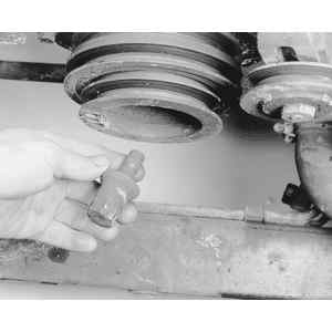
| Fig. 23: . . . remove the bolts . . .
|
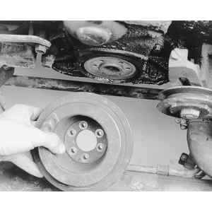
| Fig. 24: . . . and then remove the crankshaft pulley
(notice the perimeter bolt holes in the center of the pulley) — install
the center bolt back into the end of the crankshaft
|
| Fig. 25: Now remove the upper and lower timing belt cover
bolts and . . .
|
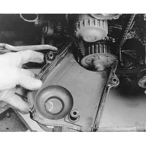
| Fig. 26: . . . remove the upper cover . . .
|
| Fig. 27: . . . then the lower cover
|
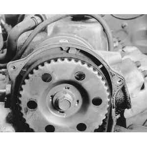
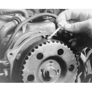
| Fig. 28: Turn the engine in the direction of normal rotation
until the letter A on the cam gear aligns with the timing mark cast into
timing belt cover mounting flange (top center)
|
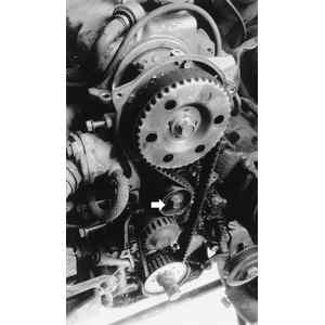
| Fig. 29: Loosen the timing belt tensioner pulley bolt
(arrow), then move the pulley away from the belt and tighten the bolt
again to lock the pulley in position — there should be
little or no tension left on the timing belt
|
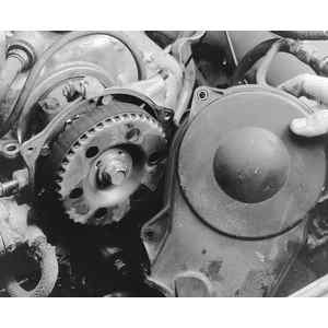
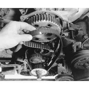
| Fig. 30: Mark the timing belt and camshaft gear . . .
|
| Fig. 31: . . . then remove the belt
|
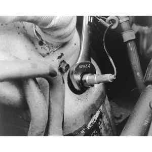
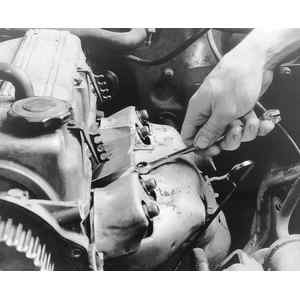
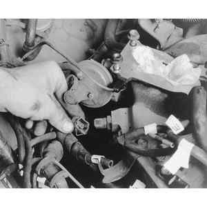
| Fig. 32: To remove the exhaust manifold, unscrew the
oxygen sensor . . .
|
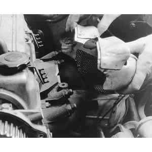
| Fig. 33: . . . then remove all the heat shield retaining
bolts . . .
|
| Fig. 34: . . . and remove the heat shield . . .
|
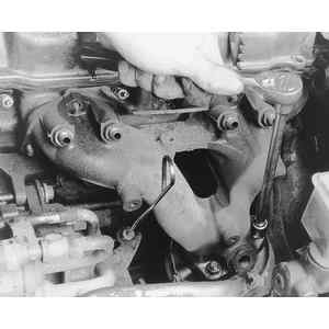
| Fig. 35: Remove the exhaust manifold-to-cylinder head
nuts . . .
|
| Fig. 36: . . . as well as the exhaust manifold-to-catalytic
converter bolts, . . .
|
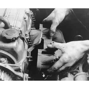
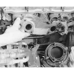
| Fig. 37: . . . then pull off the exhaust manifold . .
.
|
| Fig. 38: . . . and the old exhaust manifold gasket
|
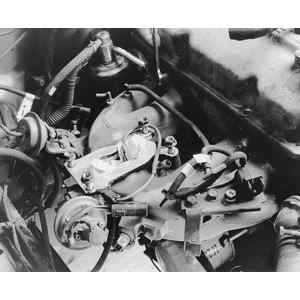
| Fig. 39: To remove the intake manifold, label and disconnect
any vacuum and electrical connections (carburetor removed for clarity)
. . .
|
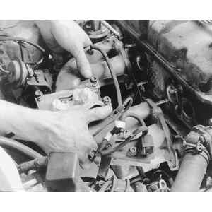
| Fig. 40: . . . then remove the intake manifold-to-cylinder
head nuts . . .
|
| Fig. 41: . . . and pull the intake manifold away from
the cylinder head. Remove the valve cover, then loosen and remove the
cylinder head bolts using the proper loosening sequence . . .
|
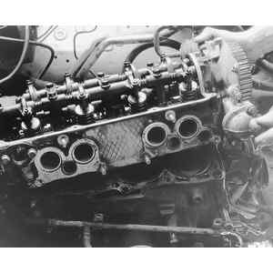
| Fig. 42: . . . then lift off the cylinder head — some
prying may be necessary, however, never hammer any object between the
cylinder head and block, as this could damage the sealing surfaces
|
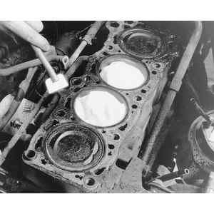
| Fig. 43: Scrape the old gasket off the block and cylinder
head surfaces, and wipe them free of any grease or oil
|
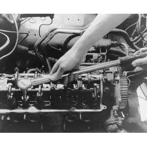
| Fig. 44: When installing the cylinder head, use an accurate
torque wrench and follow the tightening sequence and torque specifications
given
|
| Fig. 45: View of the 1,998cc engine timing belt covers
|
| Fig. 46: Camshaft pin/mark alignment on the 1,998cc engine
|
| Fig. 47: 1,998cc engine cylinder head bolt loosening
sequence
|
| Fig. 48: 1,998cc engine cylinder head bolt tightening
(torque) sequence
|
NOTE: The engine must be cold before proceeding.
CAUTION
When draining engine coolant, keep in mind that cats and dogs are attracted
to ethylene glycol antifreeze and could drink any that is left in an uncovered
container or in puddles on the ground. This will prove fatal in sufficient
quantity. Always drain coolant into a sealable container. Coolant should
be reused unless it is contaminated or is several years old.
When installing the drive belts on the various accessories, check the belt deflection as follows:
New: 7–8mm (0.276–0.315 in.)
Used: 8–9mm (0.315–0.354 in.)
New: 8–12mm (0.315–0.476 in.)
Used: 11–13mm (0.433–0.510 in.)
New: 10–12mm (0.394–0.476 in.)
Used: 12–14mm (0.476–0.552 in.)
NOTE: The engine must be cold before proceeding.
| Fig. 49: Diesel engine cylinder head bolt tightening
(torque) sequence
|
CAUTION
When draining engine coolant, keep in mind that cats and dogs are attracted
to ethylene glycol antifreeze and could drink any that is left in an uncovered
container or in puddles on the ground. This will prove fatal in sufficient
quantity. Always drain coolant into a sealable container. Coolant should
be reused unless it is contaminated or is several years old.