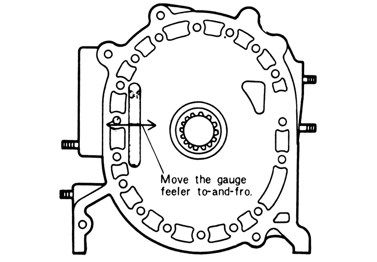
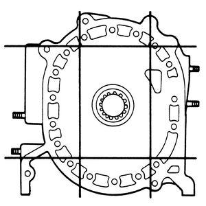
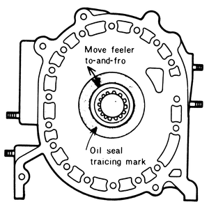
| Fig. 1: Check the housing for warpage along these lines
with a straightedge and feeler blade
|
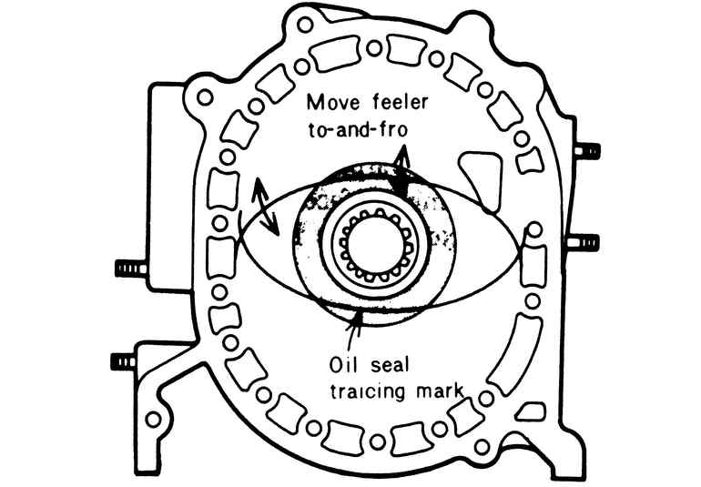
| Fig. 2: Indication of a normal wear pattern
|
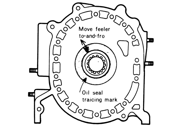
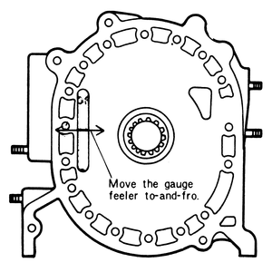
| Fig. 3: Measuring stepped wear across the middle of the
housing
|
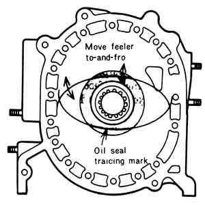
| Fig. 4: Measuring the oil seal's stepped wear
|
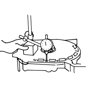
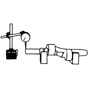
| Fig. 5: Checking the housing for wear with a dial indicator
|
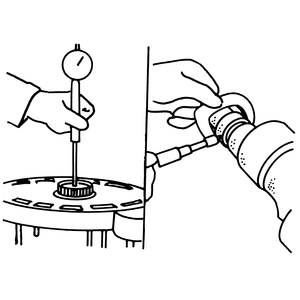
| Fig. 6: Checking the main bearing oil clearance
|
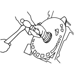
| Fig. 7: Removing the stationary gear
|
| Fig. 8: Installing the stationary gear in the rear housing
|
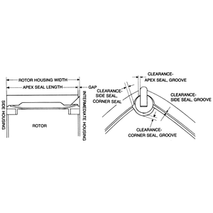
| Fig. 9: Checking the rotor housing width using a micrometer
|
- Check the housing for signs of gas or water leakage.
- Remove the carbon deposits from the front housing with an extra fine emery
cloth.
NOTE: If a carbon scraper must be used, be careful not
to damage the mating surfaces of the housing.
- Remove any old sealer which is adhering to the housing using a brush or
a cloth soaked in ketone.
- Check for distortion by placing a straightedge on the surface of the housing.
Measure the clearance between the straightedge and the housing with a feeler
gauge. If the clearance is greater than 0.05mm (0.00197 in.) at any point,
replace the housing.
- Use a dial indicator to check for wear on the rotor contact surfaces of
the housing. If the wear is greater than 0.10mm (0.00394 in.), replace the
housing.
NOTE: The wear at either end of the minor axis is greater
than at any other point on the housing. However, this is normal and should
be no cause for concern.
- Examine the teeth of the stationary gear for wear or damage.
- Be sure that the main bearing shows no signs of excessive wear, scoring
or flaking.
- Check the main bearing-to-eccentric journal clearance by measuring the journal
with a vernier caliper and the bearing with a pair of inside calipers. The
clearance should be between 0.045–0.070mm (0.00177–0.00276 in.),
and the wear limit is 0.010mm (0.000394 in.). Replace either the main bearing
or the eccentric shaft if it is greater than this. If the main bearing is
to be replaced, proceed as detailed in the following section.
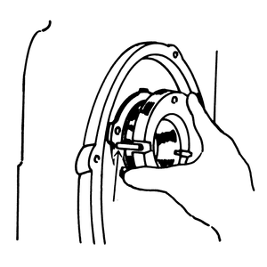
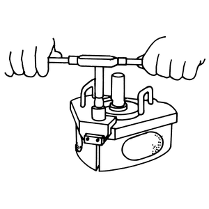
- Unfasten the securing bolts, if used. Drive the stationary gear and main
bearing assembly out of the housing with a brass drift.
- Press the main bearing out of the stationary gear.
- Press a new main bearing into the stationary gear so that it is in the same
position as the old bearing before it was removed.
- Align the slot in the stationary gear flange with the dowel pin in the housing
and press the gear into place. Install the securing bolts, if required.
NOTE: To aid in stationary gear and main bearing removal
and installation, Mazda supplies a special tool, part number 49 0813 235.
Inspection of the intermediate and rear housings is carried out in the same
manner as detailed for the front housing above. Replacement of the rear main
bearing and stationary gear (mounted on the rear housing) is given below.
Inspect the rear stationary gear and main bearing in a similar manner to the
front. In addition, examine the O-ring which is located in the stationary gear,
for signs of wear or damage. Replace the O-ring, if necessary. If required,
replace the stationary gear in the following manner:
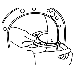
- Remove the rear stationary gear securing bolts.
- Drive the stationary gear out of the rear housing with a brass drift.
- Apply a light coating of grease on a new O-ring and fit it into the groove
on the stationary gear.
- Apply sealer to the flange of the stationary gear.
- Install the stationary gear on the housing so that the slot on its flange
aligns with the pin on the rear housing.
WARNING
Use care not to damage the O-ring during installation.
- Tighten the stationary gear bolts evenly, and in several stages, to 15 ft.
lbs.
- Examine the inner margin of both housings for signs of gas or water leakage.
- Wipe the inner surface of each housing with a clean cloth to remove the
carbon deposits.
NOTE: If the carbon deposits are stubborn, soak the cloth
in a solution made for carbon removal. Do not scrape or sand the chrome
plated surfaces of the rotor chamber.
- Clean all of the rust deposits out of the cooling passages of each rotor
housing.
- Remove the old sealer with a cloth soaked in ketone.
- Examine the chromium plate inner surfaces for scoring, flaking, or other
signs of damage. If any are present, the housing must be replaced.
- Check the rotor housing for distortion by placing a straightedge on the
areas illustrated. If the distortion exceeds 0.04mm (0.00157 in.) have the
housing refaced or replace it.
- Measure the clearance between the straightedge and the housing with a feeler
gauge. If the gap exceeds 0.05mm (0.00197 in.), replace the rotor housing.
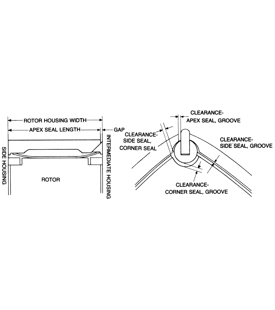
- Check the widths of both rotor housings, at a minimum of eight points near
the trochoid surfaces of each housing, with a vernier caliper. If the difference
between the maximum and minimum valves obtained is greater than 0.06mm (0.00236
in.), replace the housing. A housing in this conditions will be prone to gas
and coolant leakage.
NOTE: Standard rotor housing width is 70mm (2.7559 in.).
- Check the rotor for signs of blow-by around the side and corner seal areas.
- The color of the carbon deposits on the rotor should be brown, just as in
a piston engine.
NOTE: Usually the carbon on the leading side of the rotor
is brown, while the carbon on the trailing side tends toward black, as viewed
from the direction of rotation.
- Remove the carbon on the rotor with a scraper or extra fine emery paper.
Use the scraper carefully when doing the seal grooves, so that no damage is
done to them.
- Wash the rotor in solvent and blow it dry with compressed air after removing
the carbon.
- Examine the internal gear for cracks or damaged teeth.
NOTE: If the internal gear is damaged, the rotor and gear
must be replaced as a single assembly.
- With the oil seal removed, check the land protrusions by placing a straightedge
over the lands. Measure the gap between the rotor surface and the straightedge
with a feeler gauge. The standard specification is 0.10–0.20mm (0.00394–0.00787
in.); if it is less than this, the rotor must be replaced.
- Check the gaps between the housing and the rotor on both sides:
- Measure the rotor width with a vernier caliper. The standard rotor width
is 69.85mm (2.75 in.).
- Compare the rotor width with the width of the rotor housing measured
above. The standard rotor housing width is 70mm (2.7559 in.).
- Replace the rotor if the difference between the two measurements is
not within 0.13–0.17mm (0.0052–0.0067 in.).
- Check the rotor bearing for flaking, wearing, or scoring and proceed as
indicated in the next section, if any of these are present.
The rotors are classified into five lettered grades, according to their
weight. A letter between A and E is stamped
on the internal gear side of the rotor. If it becomes necessary to replace
a rotor, use one marked with a C because this is the standard
replacement rotor.
Special service tools are required to replace a rotor bearing. Replacement
is also a tricky procedure which, if done improperly, could result in serious
damage to the rotor and could even make replacement of the entire rotor necessary.
Therefore, this service procedure is best left to an authorized service facility
or a qualified machine shop.
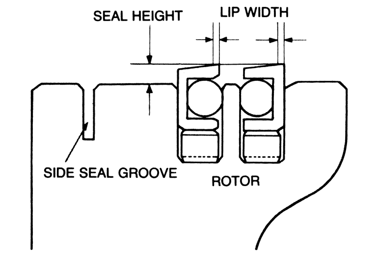
| Fig. 10: Checking the oil seals for proper height and
lip width
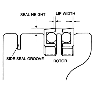
|
NOTE: Inspect the oil seal while it is mounted in the rotor.
- Examine the oil seal for signs of wear or damage.
- Measure the width of the oil seal lip. If it is greater than 0.8mm (0.0315
in.), replace the oil seal.
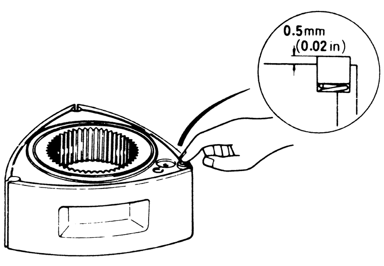
- Measure the protrusion of the oil seal, it should be greater than 0.5mm
(0.0197 in.). Replace the seal, as detailed below, if it is not.
NOTE: Replace the rubber O-ring in the oil seal as a normal
part of engine overhaul.
- Pry the seal out gently by inserting a screwdriver in the slots on the rotor.
Do not remove the seal by prying it at only one point as seal deformation
will result.
CAUTION
Be careful not to deform the lip of the oil seal if it is to be reinstalled.
- Fit both of the oil seal springs into their respective grooves, so that
their ends are facing upward and their gaps are opposite each other on the
rotor.
- Insert a new rubber O-ring into each of the oil seals.
NOTE: Before installing the O-rings into the oil seals,
fit each of the seals into its proper groove on the rotor. Check to see
that all of the seals move smoothly and freely.
- Coat the oil seal groove and the oil seal with engine oil.
- Gently press the oil seal into the groove with your fingers. Be careful
not to distort the seal.
NOTE: Be sure that the white mark is on the bottom side
of each seal when it is installed.
- Repeat the installation procedure for the oil seals on both sides of each
rotor.
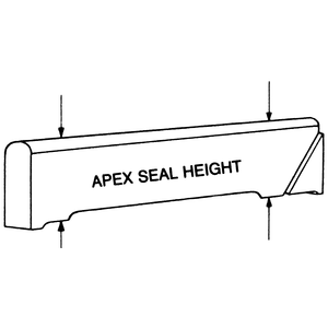
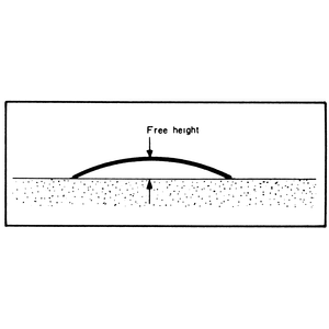
| Fig. 11: Checking the apex seal height
|
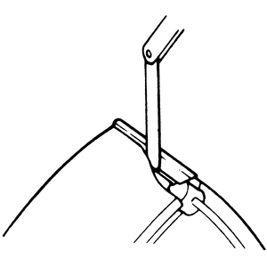
| Fig. 12: Measure the apex seal spring free height
|
| Fig. 13: Checking the gap between the apex seal and the
groove
|
| Fig. 14: Checking apex seal warpage
|
| Fig. 15: Seal clearance measurement points
|
CAUTION
Although the apex seals are extremely durable when in service, they are easily
broken when they are being handled. Be careful not to drop them.
- Remove the carbon deposits from the apex seals and their springs. Do not
use emery cloth on the seals as it will damage their finish.
- Wash the seals and the springs in cleaning solution.
- Check the apex seals for cracks and other signs of wear or damage.
- Test the seal springs for weakness.
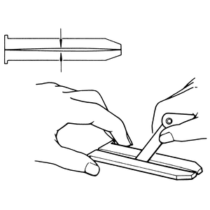
- Use a micrometer to check the seal height. Replace any seal if its height
is less than 7mm (0.276mm).
- With a feeler gauge, check the side clearance between the apex seal and
the groove in the rotor. Insert the gauge until its tip contacts the bottom
of the groove. If the gap is greater than 0.15mm (0.0059 in.), replace the
seal.
- Check the gap between the apex seals and the side housing, in the following
manner:
- Use a vernier caliper to measure the length of each apex seal.
- Compare this measurement to the minimum figure obtained when rotor housing
width was being measured.
- If the difference is more than 0.3mm (0.0118 in.), replace the seal.
The standard gap is 0.13–0.17mm (0.0052–0.0067 in.).
- If, on the other hand, the seal is too long, sand the ends of the seal
with emery cloth until the proper length is reached.
WARNING
Do not use the emery cloth on the faces of the seal!
- Remove the carbon deposits from the side seals and their springs with a
carbon scraper.
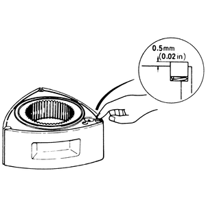
- Check the protrusion of the side seals. It should be 0.5mm (0.0197 in.)
or more.
- Check the side seals for cracks or wear. Replace any of the seals found
to be defective.
- Check the clearance between the side seals and their grooves with a feeler
gauge. Replace any side seals if they have a clearance of more than 0.10mm
(0.00394 in.). The standard clearance is 0.05–0.08mm (0.00197–0.00315
in.).
- Check the clearance between the side seals and the corner seals with both
of them installed in the rotor.
- Insert the gauge against the direction of the rotor's rotation.
- Replace the side seal if the clearance is greater than 0.4mm (0.0157
in.).
- If the side seal is replaced, adjust the clearance between it and the corner
seal as follows:
- File the side seal on its reverse side, in the same rotational direction
of the rotor, along the outline made by the corner seal.
- The clearance obtained should be 0.05–0.15mm (0.00197–0.0059
in.). If it exceeds this, the performance of the seals will deteriorate.
WARNING
There are four different types of side seals, depending upon their location.
Do not mix the seals up and be sure to use the proper type of seal for
replacement!
| Fig. 16: Checking the corner seal groove
|
- Clean the carbon deposits from the corner seals.
- Examine each of the seals for wear or damage.
- Check the corner seal protrusion from the rotor surface. It should be free
to move under the finger pressure and protrude 0.5mm (0.0197 in.) or more.
- Measure the clearance between the corner seal and its groove. The clearance
should be 0.045–0.048mm (0.00177–0.001889 in.). The wear limit
of the gap is 0.08mm (0.00315 in.).
- If the wear is between the corner seal and the groove is uneven, check the
clearance with the special bar limit gauge (Mazda part number 49 0839 165).
The gauge has a go end and a no go end. Use the gauge in the following manner:
- If neither end of the gauge goes into the groove, the clearance is within
specifications.
- If the go end of the gauge fits into the groove, but the no go end does
not, replace the corner seal with one that is 0.03mm oversize.
- If both ends of the gauge fit into the groove, then the groove must
be reamed out as detailed below. Replace the corner seal with one which
is 0.0072 in. oversize, after completing reaming.
NOTE: Take the measurement of the groove in the direction
of maximum wear, i.e., that of rotation.
| Fig. 17: Reaming the corner seal groove for an oversized
corner seal
|
NOTE: This procedure requires the use of special tools; if
attempted without them, damage to the rotor could result.
- Carefully remove all of the deposits which remain in the groove.
- Fit the jig (Mazda part number 49 2113 030) over the rotor. Tighten its
adjusting bar, being careful not to damage the rotor bearing or the apex seal
grooves.
- Use the corner seal groove reamer (Mazda part number 49 0839 170) to ream
the groove.
- Rotate the reamer at least 20 times while applying engine oil as a coolant.
NOTE: If engine oil is not used, it will be impossible
to obtain the proper groove surfacing.
- Remove the reamer and the jig.
- Repeat Steps 1–5 for each of the corner seal grooves.
- Clean the rotor completely and check it for any signs of damage.
- Fit a 0.2mm oversize corner seal into the groove and check its clearance.
Clearance should be 0.02–0.05mm (0.000787–0.00197 in.).
Check the seal springs for damage or weakness. Be exceptionally careful when
checking the spring areas which contact either the rotor or the seal.
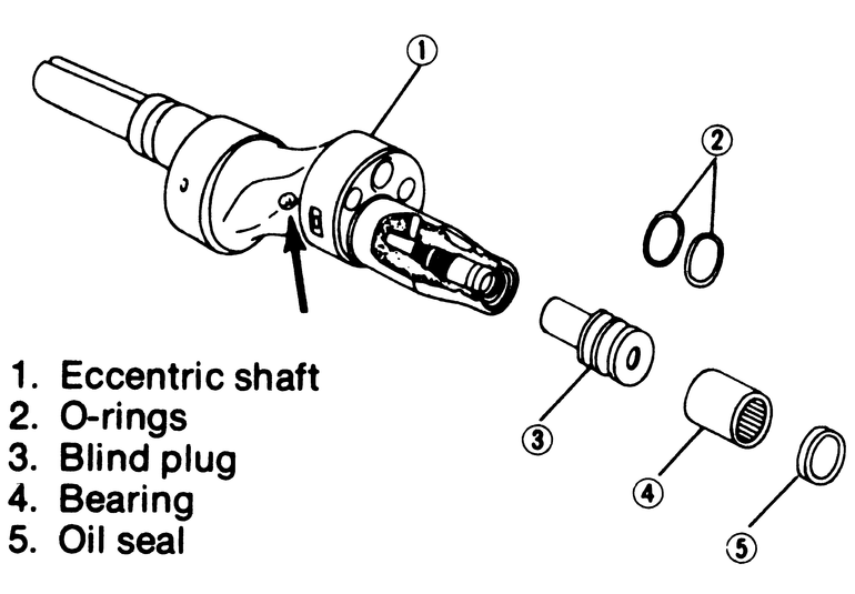
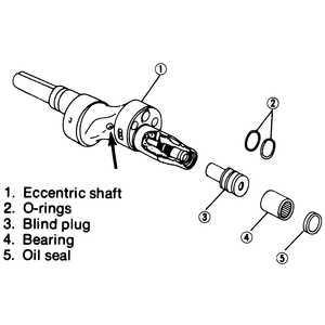
| Fig. 18:Measuring the eccentric shaft rotor journal diameter
|
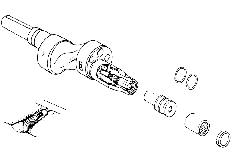
| Fig. 19: View of the eccentric shaft — arrow
points to oil jet plug; remove it to check the spring and ball
|
| Fig. 20: Using a dial indicator to check eccentric shaft
run-out
|
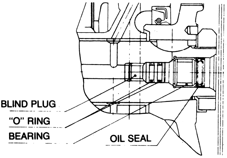
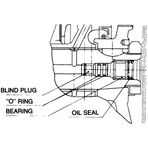
| Fig. 21: Blind plug location
|
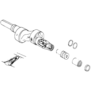
| Fig. 22: Exploded view of the roller bearing and oil
jet
|
- Wash the eccentric shaft in solvent and blow its oil passages dry with compressed
air.
- Check the shaft for wear, cracks, or other signs of damage. Make sure that
none of the oil passages are clogged.
- Measure the shaft journals with a vernier caliper. The standard specifications
are:
- Main journals — 43mm (1.6929 in.)
- Rotor journals — 74mm (2.9134 in.)
Replace the shaft if any of its journals show excessive wear.
- Check eccentric shaft run-out by placing the shaft on V-blocks and using
a dial indicator as shown. Rotate the shaft slowly and note the dial indicator
reading. If run-out is more than 0.06mm (0.00236 in.), replace the eccentric
shaft.
- Check the blind plug at the end of the shaft. If it is loose or leaking,
remove it with an allen wrench and replace the O-ring.
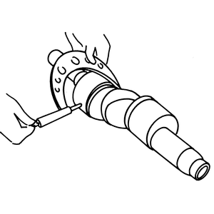
- Check the operation of the needle roller bearing for smoothness by inserting
a mainshaft into the bearing and rotating it. Examine the bearing for signs
of wear or damage.
- Replace the bearing if necessary, with the special tool, Mazda part number
49 0823 073 and 49 0823 072.