Previous Next

INSPECTION AND INSTALLATION

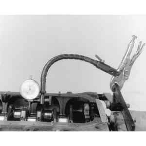
Fig. 1: A dial gauge may be used to check crankshaft end-play

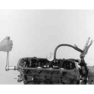
Fig. 2: Carefully pry the shaft back and forth while reading the dial gauge for play

Fig. 3: A dial gauge may also be used to check crankshaft run-out

Fig. 4: Turn the crankshaft slowly by hand while checking the gauge

Fig. 5: Mounting a dial gauge to read crankshaft run-out

Fig. 6: Another method for checking crankshaft end-play is to use a feeler blade — gently pry the crankshaft in one direction and insert the feeler blade between the crankshaft and the thrust bearing. Check the crankshaft specifications chart for proper end-play

Fig. 7: Align the thrust bearing as illustrated. Torque the caps to specifications

Fig. 8: Measure the main bearing clearance by comparing the flattened strip to the Plastigage® scale as shown

Fig. 9: Fabricate a roll-out pin as illustrated, if necessary

  1. Using a dial indicator, check the crankshaft journal runout. Measure the crankshaft journals with a micrometer to determine the correct size rod and main bearings to be used. Whenever a new or reconditioned crankshaft is installed, new connecting rod bearings and main bearings should be installed. See Main Bearings and Rod Bearings.
  2. Clean all oil passages in the block (and crankshaft if it is being reused).

    NOTE: A new rear main seal should be installed anytime the crankshaft is removed or replaced.

  3. Install sufficient oil pan bolts in the block to align with the connecting rod bolts. Use rubber bands between the bolts to position the connecting rods as required. Connecting rod position can be adjusted by increasing the tension on the rubber bands with additional turns around the pan bolts or thread protectors.
  4. Position the upper half of main bearings in the block and lubricate them with engine oil.
  5. Position crankshaft keyway in the same position as removed and lower it into block. The connecting rods will follow the crank pins into the correct position as the crankshaft is lowered.
  6. Lubricate the thrust flanges with rebuilding oil. Install caps with the lower half of the bearings lubricated with engine oil. Lubricate the cap bolts with engine oil and install, but do not tighten.
  7. With a block of wood, bump the shaft in each direction to align the thrust flanges of the main bearing. After bumping the shaft in each direction, wedge the shaft to the front and hold it while torquing the thrust bearing cap bolts.

    NOTE: In order to prevent the possibility of cylinder block and/or main bearing cap damage, the main bearing caps are to be tapped into their cylinder block cavity using a wood or rubber mallet before the bolts are installed. Do not use attaching bolts to pull the main bearing caps into their seats. Failure to observe this information may damage the cylinder block or a bearing cap.

  8. Torque all main bearing caps to specification. Check crankshaft end-play, using a flat feeler gauge.
  9. Remove the connecting rod bolt thread protectors and lubricate the connecting rod bearings with engine oil.
  10. Install the connecting rod bearing caps in their original position. Torque the nuts to specification.
  11. Complete the installation by reversing the removal steps.

Previous Next