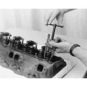
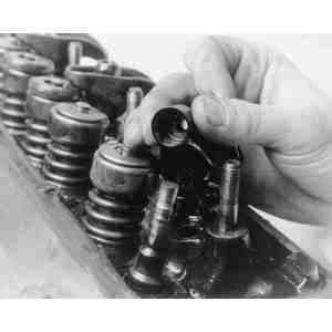
| Fig. 1: Use a valve spring compressor tool to relieve
spring tension from the valve caps
|
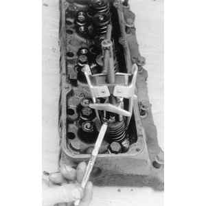
| Fig. 2: A magnet may be helpful in removing the valve
keepers
|
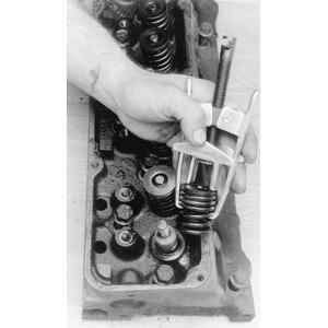
| Fig. 3: Remove the spring from the valve stem in order
to access the seal
|
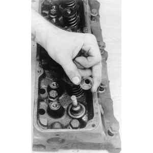
| Fig. 4: Remove the valve stem seal from the cylinder
head
|
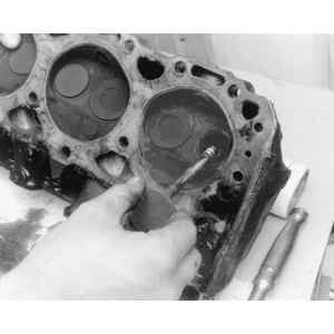
| Fig. 5: Invert the cylinder head and withdraw the valve
from the cylinder head bore
|
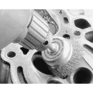
| Fig. 6: A wire wheel may be used to clean the combustion
chambers of carbon deposits
|
| Fig. 7: A dial gauge may be used to check valve stem-to-guide
clearance
|
| Fig. 8: Valve stems may be rolled on a flat surface to
check for bends
|
| Fig. 9: With the valve spring out of the way, the valve
stem seals may now be replaced
|
| Fig. 10: Use a caliper gauge to check the valve spring
free-length
|
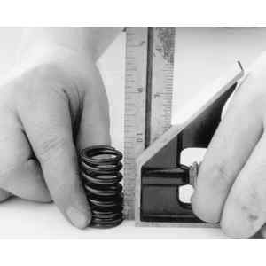
| Fig. 11: Check the valve spring for squareness on a flat
service; a carpenter's square can be used
|
| Fig. 12: The valve spring should be straight up and down
when placed like this
|
| Fig. 13: Use a micrometer to check the valve stem diameter
|
| Fig. 14: Check the cylinder head for flatness across
the head surface
|
| Fig. 15: Checks should be made both straight across the
cylinder head and at both diagonals
|
| Fig. 16: View of critical valve dimensions
|
| Fig. 17: Using a valve grinding machine to re-face an
engine valve
|
| Fig. 18: Example of a homemade valve lapping tool
|
| Fig. 19: Using a hand lapping tool to lap valves
|
| Fig. 20: Example of the marks seen on the valve tips
for valves with rotators
|
| Fig. 21: Testing the valve spring pressure
|
| Fig. 22: Measuring valve spring installed height — the
measurement is taken from the spring seat (cylinder head), to the top
of the spring (bottom edge of the spring retainer)
|
| Fig. 23: Measure the springs' free length — there
should be no more than 5/64 inch (0.078 inches) variation between springs
|
| Fig. 24: View of the valve and spring components — not
shown are the valve keepers, which sit in the center of the retainer and
lock around the valve
|
| Fig. 25: View of a typical valve seal — be
sure to push the new seal firmly over the valve guide
|
| Fig. 26: Using a valve guide driver to install a new
valve guide into the head
|
| Fig. 27: Checking valve seat concentricity
|
NOTE: Consult the Specifications tables earlier in this chapter.