Be sure that the air pump drive belt is adjusted to the proper tension. See
Section 1.
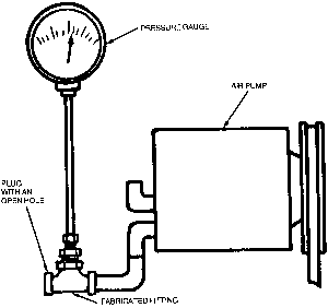
| Fig. 1: An example of connecting an air pressure gauge
to the air pump outlet in order to check outlet pressure — if
the reading is under 1 psi, replace the pump
|
- Disconnect the air pump outlet hose from the air by-pass valve.
- Connect a T-fitting and pressure gauge into the outlet line. The other end
of the fitting should have a plug with an 11⁄32 "
hole drilled through it.
- Start the engine and run it briefly at 1,500 rpm. Be sure the choke is fully
open (pushed in).
- If the pressure reading is below 1 psi, replace the pump.
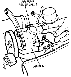
| Fig. 2: Example of how to check the air pump relief valve
|
- Operate the engine at idle.
- Check the relief valve for airflow. No flow should be evident. If airflow
out is noted, replace the relief valve and air pump.
- Increase the engine speed to 3,000 rpm (4,500 rpm, 1978 and later). If air
flows out of the relief valve, the valve is in good condition. If air does
not flow from the relief valve, or if the valve is excessively noisy, the
relief valve and air pump assembly should be replaced.
Remove the check valve from the air injection manifold. Blow through the valve
from the intake side of the outlet side. Air should pass through the valve from
the intake side only. If air passes through the valve from the outlet side,
replace the valve.
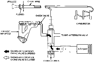
| Fig. 3: Diagram of air bypass valve operation for 1972–74
trucks
|
- Disconnect the air line at the check valve.
- Push the choke knob all the way in.
- Run the engine at 1,500 rpm.
- Hold your hand over the end of the air pump air line. Air should flow from
the hose.
- Pull the choke knob all the way out. No air should flow from the air line.
- If the valve is not operating properly, replace the valve.
- Disconnect the outlet hose from the bottom of the air control valve at the
air cleaner. Start the engine and let it idle. Air should not be discharged
from the outlet.
- Unplug the air control valve solenoid electrical connector. With the engine
still idling, check for air discharge from the valve outlet.
- Reconnect the electrical connectors. Increase the engine speed above 4,000
rpm (4,300 with automatic transmission), and check that air is discharged
from the valve outlet. When the engine speed falls, the air discharge should
stop.
- If the valve is not operating properly, check the hoses for leaks, breaks,
kinks, or improper connections. Replace the valve as necessary.
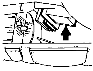
| Fig. 4: The control unit is located on the kick panel,
beneath the parking brake lever
|
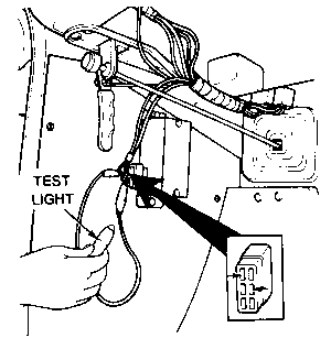
| Fig. 5: Connecting a test light to the 1975–76
air injection control unit
|
- Attach a test light to the unit connector as shown.
- Start the engine. The light should be on with the engine idling.
- Increase the speed above 4,000 rpm (4,300 with automatic transmission).
The light should go off.
- If the light does not go off when specified, or does not remain on with
the engine idling, replace the unit.
This procedure is for all 1,796cc engines. Only California trucks have this
valve.
- Disconnect the outlet hose at the bottom of the valve. Start the engine
and let it idle.
- Check that air is not discharged from the outlet.
- Disconnect the small diameter hose from the top of the valve. Air should
now be felt at the valve outlet.
- If the valve is not operating properly, check the hoses for leaks, kinks,
breaks, or improper connections, and inspect the check valve for proper operation.
Replace the air control valve if necessary. Reconnect the hoses after the
test.
This test is for all 1980 models sold in California with a manual transmission.
- Warm the engine to normal operating temperature, then shut it off.
- Disconnect the air hose at the bottom of the air control valve. Start the
engine and allow it to idle.
- Disconnect the thin vacuum hose from the top of the air control valve. This
is the hose which runs to the intake manifold. Air should be discharged from
the air control valve outlet. Connect the hose again; the airflow from the
outlet should stop.
- Disconnect the vacuum sensing hose (which connects to the No. 2 relief valve
on the side of the air control valve) at the T-fitting.
- Obtain a T fitting and a length of vacuum hose. Disconnect the vacuum hose
from the top of the air control valve (same hose as disconnected in Step 3).
Connect this hose to the T-fitting and the hose fitting on the top of the
air control valve from which the other length of hose (intake manifold vacuum
hose) was just removed. You should now have a T-fitting with two hoses connected
to it: one running from the top of the air control valve to the T-fitting,
and the other running from the intake manifold to the T-fitting.
- Connect the No. 2 relief valve vacuum hose (disconnect from its own T-fitting
in Step 4) to the T-fitting. This will allow the No. 2 relief valve to be
directly connected to intake manifold vacuum.
- With the engine idling, air should be discharged from the outlet of the
air control valve.
- Disconnect and plug the vacuum hose from the No. 2 relief valve fitting
(on the side of the air control valve). Airflow from the air control valve
should stop.
- If the air control valve does not operate correctly, replace it.
This is a test for the check valve installed in the hose which runs from the
air cleaner case to the exhaust manifold, on 1979 and later 49 State models
without an air pump.
- Warm the engine to normal operating temperature, then shut it off.
- Disconnect the air hose from the check valve.
- Start the engine and allow it to idle.
- Place a finger over the check valve inlet; vacuum should be felt. If no
air is being drawn into the valve, replace the valve.
- Run the engine up to about 1,500 rpm. Check for exhaust gas leakage at the
check valve air inlet fitting. If leakage is present, replace the valve.

