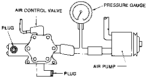
| Fig. 1: Test connections for the air pump on rotary engines

|
- Check the air pump drive belt tension by applying 22 lbs. of pressure halfway
between the water pump and air pump pulleys. The belt should deflect 6–9mm
(0.236–0.354 in.). Adjust the belt if necessary, or replace it if it
is cracked or worn.
- Turn the pump by hand. If it has seized, the drive belt will slip, producing
noise.
NOTE: Disregard any chirping squealing, or rolling sounds
coming from inside the pump; these are normal when it is being turned by
hand.
- Check the hoses and connections for leaks. Hissing or a blast of air is
indicative of a leak. Soapy water, applied around the area in question, is
a good method of detecting leaks.
- Connect a pressure gauge between the air pump and the air control valve
with a T-fitting.
- Plug the other hose connections (outlets) on the air control valve, as illustrated.
CAUTION
Be careful not to touch the thermal reactor; severe burns will result.
- With the engine at normal idle speed, the pressure gauge should read 0.48–0.68
psi. Replace the air pump if it is less than this.
- If the air pump is not defective, leave the pressure gauge connected but
unplug the connections at the air control valve and proceed with the next
test.
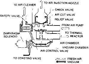
| Fig. 2: Cross-section of the air control valve

|
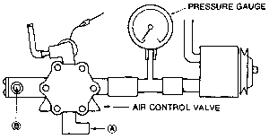
| Fig. 3: Test connections for the air control valve

|
CAUTION
When testing the air control valve, avoid touching the thermal reactor as severe
burns will result.
- Test the air control valve solenoid as follows:
- Turn the ignition switch off and on. A click should be heard coming
from the solenoid. If no sound is audible, check the solenoid wiring.
- If no defect is found in the solenoid wiring, connect the solenoid directly
to the truck's battery. If the solenoid still does not click, it is defective
and must be replaced. If the solenoid works, then check the components
of the air flow control system. See below.
- Start the engine and run it at idle speed. The pressure gauge should still
read 0.37–0.75 psi. No air should leak from the two outlets which were
unplugged.
- Increase the engine speed to 3,500 rpm for manual transmissions; 3,000 rpm
for automatic transmissions. The pressure gauge should now read 1.2–2.8
psi and the two outlets still should not be leaking air.
- Return the engine to idle.
- Disconnect the solenoid wiring. Air should now flow from the outlet marked
A in the illustration, but not from the outlet marked B. The pressure gauge
reading should remain the same as in Step 2.
- Reconnect the solenoid.
- If the relief valve is faulty, air sent from the air pump will flow into
the cooling passages of the thermal reactor when the engine is at idle speed.
- If the safety valve is faulty, air will flow into the air cleaner when the
engine is idling.
- Replace the air control valve if it fails to pass any one of the above tests.
Remember to disconnect the pressure gauge.
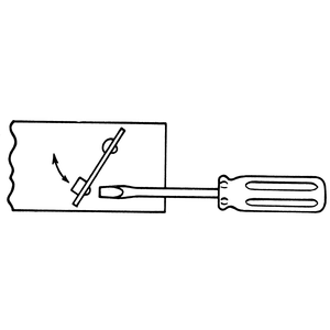
| Fig. 4: Check the one-way valve operation, as illustrated

|
- Remove the check valve, as detailed below.
- Depress the valve plate to see if it will seat properly.
- Measure the free length of the valve spring; it should be 31mm (1.22 in.)
on trucks with manual transmission; 19mm (0.748 in.) on trucks with automatic
transmission.
- Measure the installed length of the spring; it should be 17mm (0.669 in.).
Replace the check valve if it is not up to specifications.

