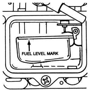
| Fig. 1: Fuel level mark on the sight glass of 1,586cc,
1,796cc and 1,970cc engines
|
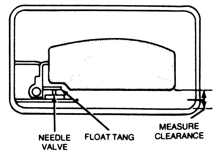
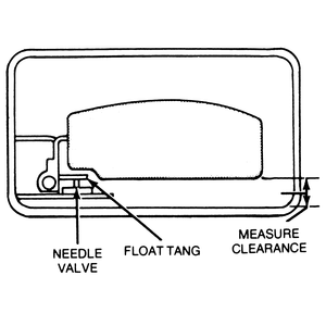
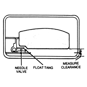
| Fig. 2: Float level adjustment. Measure the clearance
between the float and the edge of the bowl on 1,586cc, 1,796cc and 1,970cc
engines
|
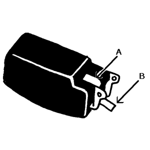
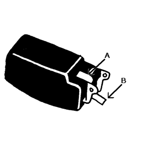
| Fig. 3: Bend the tang to adjust the float level — bend
point (A) to correct float level and point (B) to correct float drop on
1,586cc, 1,796cc and 1,970cc engines
|
- With the engine running, check the fuel level in the sight glass (in the
fuel bowl).
- If the fuel level is not at the specified mark on the sight glass, remove
the carburetor from the truck.
- Remove the fuel bowl cover.
- Invert the carburetor and lower the float until the tang on the float just
contacts the needle valve.
- Measure the clearance between the float and the edge of the bowl. Clearance
should be:
- 1,586cc — 0.65mm (0.0256 in.)
- 1,796cc — 0.60mm (0.0236 in.)
- 1,970cc — 0.85mm (0.0334 in.)
- If the clearance is not as specified, bend the float seal lip until the
proper clearance is obtained.
- Turn the carburetor right side up and measure the clearance between the
bottom of the float and the bowl. Clearance should be:
- 1,586cc and 1,796cc — 1.2mm (0.0472 in.)
- 1,970cc — 1.0mm (0.0394 in.)
- If not, bend the float stopper until the correct clearance is obtained.
- Install the fuel bowl cover.
- Reinstall the carburetor on the truck.
- Recheck the fuel level at the sight glass.
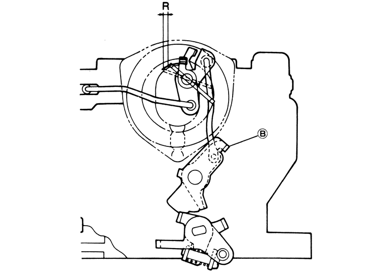
| Fig. 4: 1,998cc engine float level adjustment — bend
point (a) to correct float level and point (b) to correct float drop

|
| Fig. 5: 1,998cc engine float drop adjustment — see
Fig. 11
|
- Remove the air horn from the carburetor.
- Turn the air horn upside down on a level surface. Allow the float to hang
under its own weight.
- Measure the clearance between the float and the air horn gasket surface.
The gap should be 11.5–12.5mm (0.4528–0.4921 in.). If not, bend
the float seat lip to obtain the correct gap.
- Turn the air horn right side up and allow the float to hang under its own
weight.
- Measure the gap between the BOTTOM of the float and the air horn gasket
surface. The gap should be 46.0–47.0mm (1.811–1.850 in.). If not,
bend the float stopper until it is.
| Fig. 6: Checking the fuel level in the sight glass on
the rotary engine
|
| Fig. 7: Checking the float level with the air horn removed
on the rotary engine
|
- With the engine running, check the fuel level in the sight glass, using
a mirror.
- If the fuel levels are not within the specified marks on the sight glass,
remove the air horn with the floats.
- Invert the air horn and let the float hang so that it just contacts the
needle valve.
- Measure the clearance between the float and the air horn gasket, which should
be 1.1mm (0.0433 in.). Bend the float seat lip to adjust the clearance if
necessary.
- Install the air horn and recheck the fuel levels in the sight glass.
| Fig. 8: Checking the float drop on the rotary engine
|
| Fig. 9: Rotary engine float adjustment points — point
(A) is for float level adjustment and point (B) is for float drop adjustment
|
- Remove the air horn with the floats and allow the floats to hang free.
- Measure the clearance between the bottom of the float and the air horn gasket.
The clearance should be 51.5–52.5mm (2.028–2.067 in.).
- If not, adjust the distance by bending the float stopper.
- Install the air horn and recheck the fuel level in the sight glass.
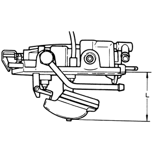
| Fig. 10: 1,586cc engine fast idle adjusting screw location
(inset-arrow)
|
The fast idle can be adjusted by turning the fast idle adjusting screw. Check
the choke plate for free operation.
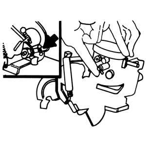
| Fig. 11: Fast idle adjustment points for 1,796cc engine
carburetors. Bend the link at the point indicated by the arrow
|
- Remove the air cleaner.
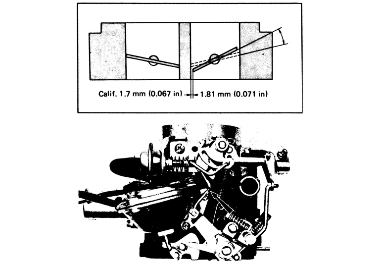
- With the choke plate fully closed, measure the clearance between the primary
throttle plate and the wall of the throttle bore. The clearance should measure
1.6–1.7mm (0.0629–0.0669 in.) through 1976, and 1.8mm (0.0708
in.) in 1977–78, or 2.5mm (0.0984 in.) for 1977–78 California
models.
- If the clearance is not as specified, bend the fast idle lever where it
contacts the throttle lever tang until the proper clearance is obtained.
- Install the air cleaner.
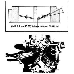
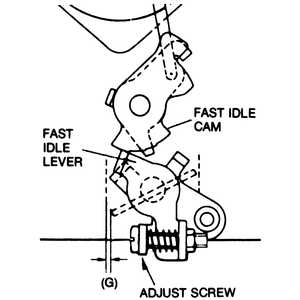
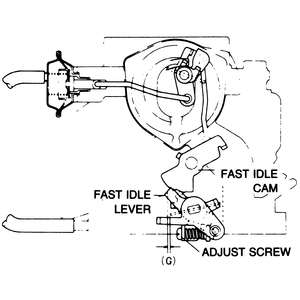
| Fig. 12: Fast idle adjustment for the 1,970cc carburetor
|
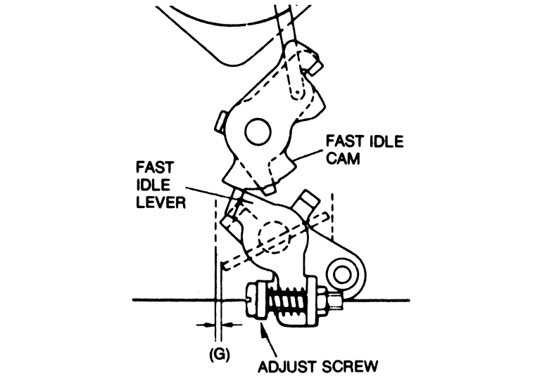
- Close the choke fully.
- Place the fast idle adjusting screw on the first step of the fast idle cam.
- Check the clearance between the throttle plate and the inside of the throttle
wall (G) with a wire feeler gauge. It should measure 1.3–1.5mm (0.0512–0.0590
in.).
- If the clearance is incorrect, adjust by means of the fast idle screw, clockwise
to increase or counterclockwise to decrease.
| Fig. 13: Fast idle adjustment for the 1,998cc engine
|
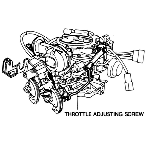
| Fig. 14: Throttle adjusting screw on the 1,998cc engine
|
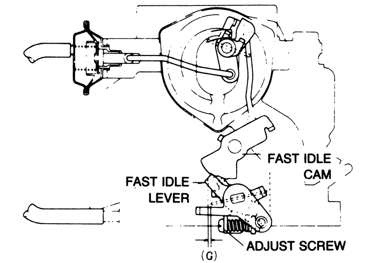
- Set the fast idle cam so that the fast idle lever rests on the second step
of the cam.
- Adjust the clearance between the air horn wall and the lower edge of the
throttle plates, (G) by turning the fast idle adjusting screw. Clearance should
be 0.75–1.13mm (0.0295–0.0445 in.)
| Fig. 15: Fast idle adjustment on the rotary engine carburetor.
Bend the rod at the point indicated by the arrow until the proper rpm
is attained

|
- Pull the choke knob all the way out.
- Measure the clearance between the primary throttle plate and the wall of
the primary throttle bore. The clearance can be measured with a suitable drill
bit.
- The clearance should be 1.0–1.3mm (#61–#55 drill) for trucks
with manual transmission, or 1.2–1.5mm (#55–#53 drill) for trucks
with automatic transmission.
- If the clearance is not as specified, adjust the fast idle by bending the
connecting rod to obtain the proper clearance.
Inspect the throttle linkage for free operation. Remove the air cleaner. With
the accelerator fully depressed, the position of the throttle plates should
be vertical.
- Loosen the locknuts on the longer linkage rod and rotate both ends in the
sockets until the proper accelerator travel from idle to wide-open throttle
is obtained.
- Tighten the locknuts to set the adjustment.
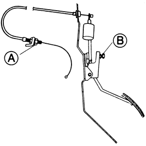
| Fig. 16: Accelerator cable adjustments are made using
the adjuster nuts (arrows) — vehicles not equipped with
cruise control have only one cable
|
| Fig. 17: Throttle cable adjustment points for the 1,998cc
engine
|
- Check the cable deflection at the carburetor. Deflection should be 1.0–3.0mm
(0.0394–0.1181 in.). If not, adjust it by turning the adjusting nut
at the bracket near the carburetor.
- Depress the accelerator pedal to the floor. The throttle plates should be
vertical. If not, adjust their position by turning the adjusting nut on the
accelerator pedal bracket.
| Fig. 18: Bend tab (B) to adjust the secondary throttle
valve on 1986 models
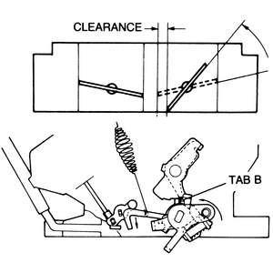
|
The clearance between the primary throttle valve and the air horn wall, when
the secondary throttle valve just starts to open should be:
- 1,586cc — 5.00–5.60mm (0.1968–0.2204 in.)
- 1,796cc — 4.70–5.30mm (0.1850–0.2086 in.)
- 1,970cc — 6.10–6.85mm (0.2402–0.2697 in.)
- 1,998cc — 7.30–8.30mm (0.2874–0.3268 in.)
If not, bend the fast idle link (1972–84) or the tab B (1986 illustrated).
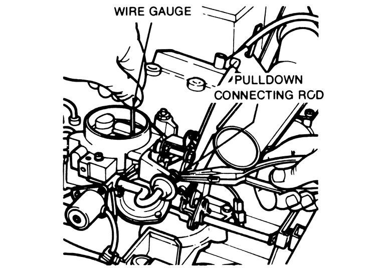
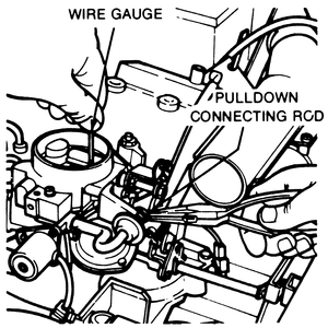
| Fig. 19: Vacuum pulldown adjustment
|
- On California Mazdas, unplug the electrical connectors from the water thermo
switch and connect a jumper wire between the connectors. Turn the ignition
switch on.
- Pull the choke knob out to fully close the choke.
- Disconnect the vacuum source to the pulldown diaphragm.
- Connect an external vacuum source to the pulldown diaphragm. Gradually apply
vacuum. The pulldown should start to operate (open the choke) at 5.9–7.5
in.Hg.
- Increase the vacuum to 9.8–12.0 in.Hg. Check the clearance between
the carburetor air horn wall and the choke plate using a wire gauge. The clearance
should measure 1.5–2.0mm (0.059–0.787 in.) for 1976; 1.6–1.9mm
(0.063–0.075 in.) for 1977–78.
- Adjust the clearance if necessary by bending the pulldown connecting rod.
| Fig. 20: Choke adjustment for 1,586cc and 1,796cc engine
carburetors
|
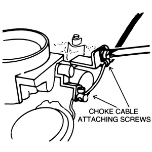
- Push the choke knob all the way in.
- Loosen the choke cable attaching screws at the choke lever and the choke
cable bracket.
- Be sure that the choke plate is fully open.
- Insert the choke cable into the choke lever. Tighten the attaching screw.
- Pull the cable outward to remove all slack between the choke lever and choke
cable bracket and tighten the attaching screw at the choke cable bracket.
- Operate the choke to be sure that there is no binding and that it is operating
properly.
There are four adjustments to be made to the choke in these years; choke/throttle
valve opening adjustment; choke diaphragm adjustment; choke unloader adjustment;
and choke thermostat (bi-metal) adjustment.
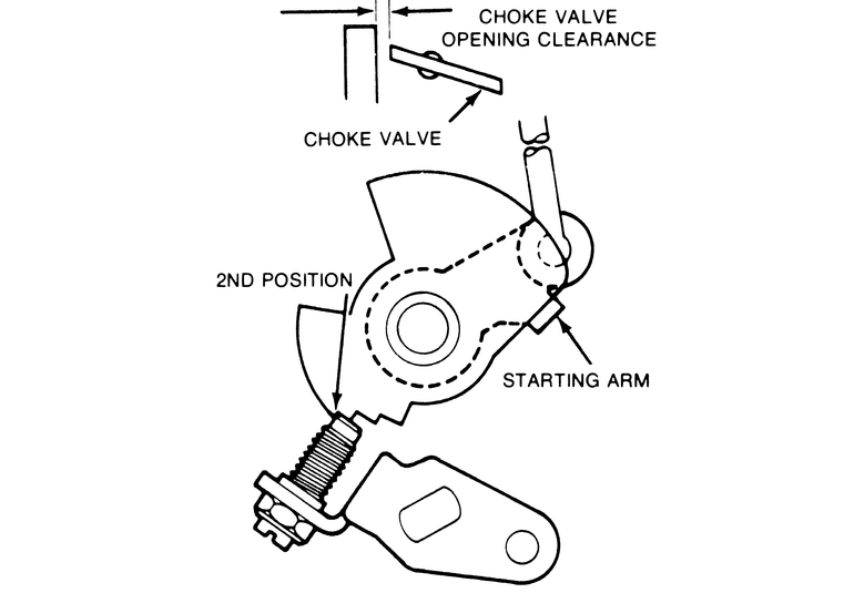
| Fig. 21: 1,970cc engine choke throttle valve opening
adjustment
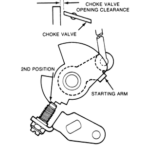
|
- Adjust the fast idle cam as previously outlines before making this adjustment.
- Place the fast idle screw on the second step of the fast idle cam.
- Measure the clearance between the edge of the choke plate and the throttle
bore with a wire gauge. Clearance should be 0.4–0.7mm (0.0157–0.0276
in.).
- If the clearance is incorrect, adjust by bending the starting arm. If a
large adjustment is required, the choke rod can be bent slightly.
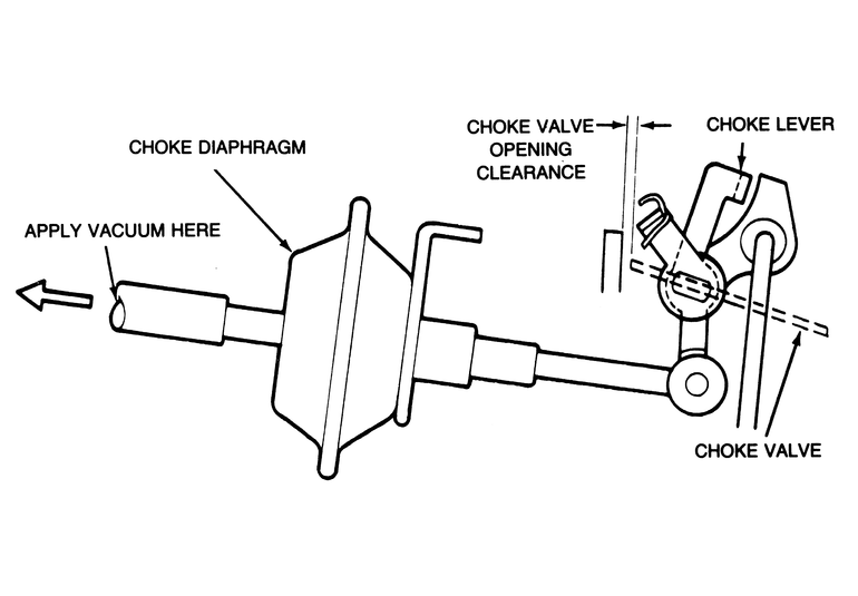
| Fig. 22: 1,970cc engine choke diaphragm adjustment

|
- Remove the vacuum hose from the choke diaphragm. Attach a vacuum pump to
the diaphragm fitting and apply approximately 15.6 in. Hg to the diaphragm.
- Check to see that the fast idle screw is on the first step of the fast idle
cam.
- Press on the choke plate slightly to settle it. Measure the clearance between
the edge of the choke plate and the throttle bore. Clearance should be 1.2–1.7mm
(0.047–0.067 in.).
- If the clearance is incorrect, adjust by bending the choke lever.
| Fig. 23: 1,970cc engine choke unloader adjustment
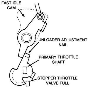
|
- Close the choke plate fully. Open the throttle plate fully.
- Measure the clearance between the edge of the choke plate and the throttle
bore with a wire gauge. Clearance should be 2.0–2.5mm (0.0787–0.9843
in.).
- If the clearance is incorrect, bend the choke unloader adjusting nail (tang).
| Fig. 24: 1,970cc engine choke thermostat adjustment
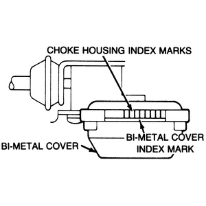
|
- The index mark on the thermostat cover should be aligned with the center
mark on the choke housing.
- Adjust by loosening the thermostat cover retaining screws slightly and shifting
the position of the cover. Tighten the screws after adjustment.
Three choke related adjustments are performed on these units.
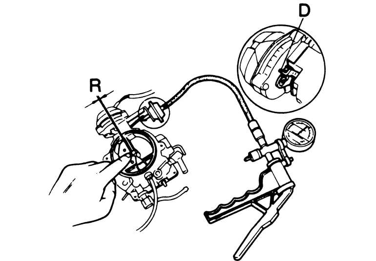
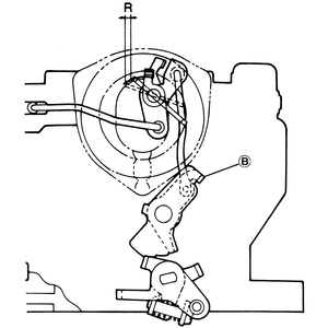
| Fig. 25: 1,998cc engine choke diaphragm adjustment

|
- Disconnect the vacuum line from the choke diaphragm unit.
- Using a vacuum pump, apply 15.7 in. Hg to the diaphragm.
- Using light finger pressure, close the choke valve. Check the clearance
at the upper edge of the choke valve. Clearance should be 1.6–2.1mm
(0.063–0.083 in.).
- If not, bend the tab on the choke lever to adjust it.
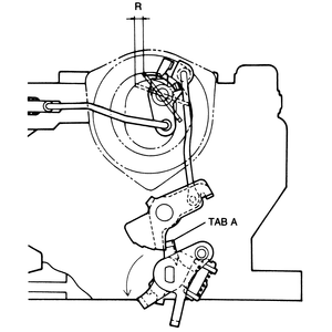
| Fig. 26: 1,998cc engine choke valve clearance adjustment
|
- Position the fast idle lever on the second step of the fast idle cam.
- The leading edge of the choke valve should be 0.60–1.0mm (0.024–0.039
in.) from fully closed. If not, bend either the tab on the cam or the choke
rod to adjust. The tab will give smaller adjustment increments.
| Fig. 27: 1,998cc engine choke unloader adjustment
|
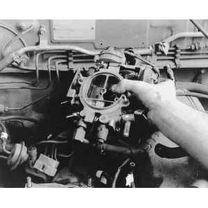
| Fig. 28: Label and remove all vacuum lines to the carburetor
. . .
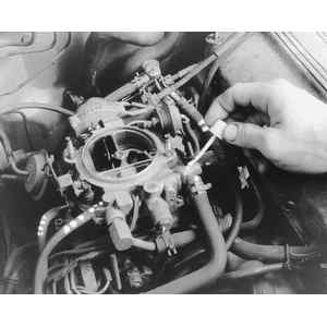
|
| Fig. 29: . . . then label and remove all electrical connections
to the carburetor
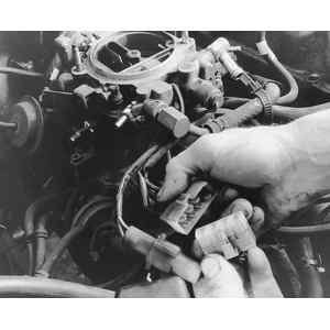
|
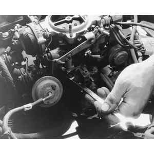
| Fig. 30: Remove any clips retaining the accelerator cables
and pull them free of their brackets . . .
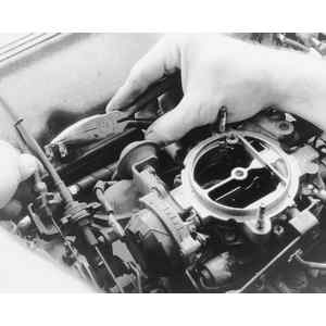
|
| Fig. 31: . . . then remove the cables from the throttle
shaft
|
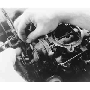
| Fig. 32: Loosen and remove the carburetor mounting bolts
. . .
|
| Fig. 33: . . . and lift off the carburetor assembly
|
- Open the primary throttle valve all the way and hold it in this position.
- The leading edge of the choke valve should be 2.74–3.60mm (0.1079–0.1417
in.) from fully closed. If not, bend the tab on the throttle lever.