Soldering is a quick, efficient method of joining metals permanently. Everyone who has the occasion to make wiring repairs should know how to solder. Electrical connections that are soldered are far less likely to come apart and will conduct electricity much better than connections that are only ``pig-tailed'' together. The most popular (and preferred) method of soldering is with an electrical soldering gun. Soldering irons are available in many sizes and wattage ratings. Irons with higher wattage ratings deliver higher temperatures and recover lost heat faster. A small soldering iron rated for no more than 50 watts is recommended, especially on electrical systems where excess heat can damage the components being soldered.
There are three ingredients necessary for successful soldering; proper flux, good solder and sufficient heat. A soldering flux is necessary to clean the metal of tarnish, prepare it for soldering and to enable the solder to spread into tiny crevices. When soldering, always use a rosin core solder which is non-corrosive and will not attract moisture once the job is finished. Other types of flux (acid core) will leave a residue that will attract moisture and cause the wires to corrode. Tin is a unique metal with a low melting point. In a molten state, it dissolves and alloys easily with many metals. Solder is made by mixing tin with lead. The most common proportions are 40/60, 50/50 and 60/40, with the percentage of tin listed first. Low priced solders usually contain less tin, making them very difficult for a beginner to use because more heat is required to melt the solder. A common solder is 40/60 which is well suited for all-around general use, but 60/40 melts easier and is preferred for electrical work.
Successful soldering requires that the metals to be joined be heated to a temperature that will melt the solder, usually 360–460°F (182–238°C). Contrary to popular belief, the purpose of the soldering iron is not to melt the solder itself, but to heat the parts being soldered to a temperature high enough to melt the solder when it is touched to the work. Melting flux-cored solder on the soldering iron will usually destroy the effectiveness of the flux.
NOTE: Soldering tips are made of copper for good heat conductivity, but must be ``tinned'' regularly for quick transference of heat to the project and to prevent the solder from sticking to the iron. To ``tin'' the iron, simply heat it and touch the flux-cored solder to the tip; the solder will flow over the hot tip. Wipe the excess off with a clean rag, but be careful as the iron will be hot.
After some use, the tip may become pitted. If so, simply dress the tip smooth with a smooth file and ``tin'' the tip again. Flux-cored solder will remove oxides but rust, bits of insulation and oil or grease must be removed with a wire brush or emery cloth. For maximum strength in soldered parts, the joint must start off clean and tight. Weak joints will result in gaps too wide for the solder to bridge.
If a separate soldering flux is used, it should be brushed or swabbed on only those areas that are to be soldered. Most solders contain a core of flux and separate fluxing is unnecessary. Hold the work to be soldered firmly. It is best to solder on a wooden board, because a metal vise will only rob the piece to be soldered of heat and make it difficult to melt the solder. Hold the soldering tip with the broadest face against the work to be soldered. Apply solder under the tip close to the work, using enough solder to give a heavy film between the iron and the piece being soldered, while moving slowly and making sure the solder melts properly. Keep the work level or the solder will run to the lowest part and favor the thicker parts, because these require more heat to melt the solder. If the soldering tip overheats (the solder coating on the face of the tip burns up), it should be retinned. Once the soldering is completed, let the soldered joint stand until cool. Tape and seal all soldered wire splices after the repair has cooled.
Most connectors in the engine compartment or that are otherwise exposed to the elements are protected against moisture and dirt which could create oxidation and deposits on the terminals.
These special connectors are weather-proof. All repairs require the use of a special terminal and the tool required to service it. This tool is used to remove the pin and sleeve terminals. If removal is attempted with an ordinary pick, there is a good chance that the terminal will be bent or deformed. Unlike standard blade type terminals, these weather-proof terminals cannot be straightened once they are bent. Make certain that the connectors are properly seated and all of the sealing rings are in place when connecting leads. On some models, a hinge-type flap provides a backup or secondary locking feature for the terminals. Most secondary locks are used to improve connector reliability by retaining the terminals if the small terminal lock tangs are not positioned properly.
Molded-on connectors require complete replacement of the connection. This means splicing a new connector assembly into the harness. All splices should be soldered to insure proper contact. Use care when probing the connections or replacing terminals in them as it is possible to short between opposite terminals. If this happens to the wrong terminal pair, it is possible to damage certain components. Always use jumper wires between connectors for circuit checking and never probe through weatherproof seals.
Open circuits are often difficult to locate by sight because corrosion or terminal misalignment are hidden by the connectors. Merely wiggling a connector on a sensor or in the wiring harness may correct the open circuit condition. This should always be considered when an open circuit or a failed sensor is indicated. Intermittent problems may also be caused by oxidized or loose connections. When using a circuit tester for diagnosis, always probe connections from the wire side. Be careful not to damage sealed connectors with test probes.
All wiring harnesses should be replaced with identical parts, using the same gauge wire and connectors. When signal wires are spliced into a harness, use wire with high temperature insulation only. It is seldom necessary to replace a complete harness. If replacement is necessary, pay close attention to insure proper harness routing. Secure the harness with suitable plastic wire clamps to prevent vibrations from causing the harness to wear in spots or contact any hot components.
NOTE: Weatherproof connectors cannot be replaced with standard connectors. Instructions are provided with replacement connector and terminal packages. Some wire harnesses have mounting indicators (usually pieces of colored tape) to mark where the harness is to be secured.
In making wiring repairs, its important that you always replace damaged wires with wiring of the same gauge as the wire being replaced. The heavier the wire, the smaller the gauge number. Wires are color-coded to aid in identification and whenever possible the same color coded wire should be used for replacement. A wire stripping and crimping tool is necessary to install solderless terminal connectors. Test all crimps by pulling on the wires; it should not be possible to pull the wires out of a good crimp.
Wires which are open, exposed or otherwise damaged are repaired by simple splicing. Where possible, if the wiring harness is accessible and the damaged place in the wire can be located, it is best to open the harness and check for all possible damage. In an inaccessible harness, the wire must be bypassed with a new insert, usually taped to the outside of the old harness.
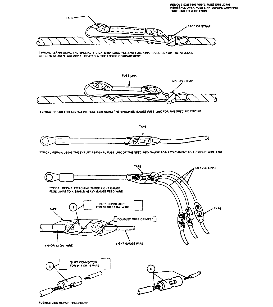
When replacing fusible links, be sure to use fusible link wire, NOT ordinary automotive wire. Make sure the fusible segment is of the same gauge and construction as the one being replaced and double the stripped end when crimping the terminal connector for a good contact. The melted (open) fusible link segment of the wiring harness should be cut off as close to the harness as possible, then a new segment spliced in as described. In the case of a damaged fusible link that feeds two harness wires, the harness connections should be replaced with two fusible link wires so that each circuit will have its own separate protection.
NOTE: Most of the problems caused in the wiring harness are due to bad ground connections. Always check all vehicle ground connections for corrosion or looseness before performing any power feed checks to eliminate the chance of a bad ground affecting the circuit.
Unlike molded connectors, the terminal contacts in hard-shell connectors can be replaced. Weatherproof hard-shell connectors with the leads molded into the shell have non-replaceable terminal ends. Replacement usually involves the use of a special terminal removal tool that depresses the locking tangs (barbs) on the connector terminal and allows the connector to be removed from the rear of the shell. The connector shell should be replaced if it shows any evidence of burning, melting, cracks, or breaks. Replace individual terminals that are burnt, corroded, distorted or loose.
NOTE: The insulation crimp must be tight to prevent the insulation from sliding back on the wire when the wire is pulled. The insulation must be visibly compressed under the crimp tabs, and the ends of the crimp should be turned in for a firm grip on the insulation.
The wire crimp must be made with all wire strands inside the crimp. The terminal must be fully compressed on the wire strands with the ends of the crimp tabs turned in to make a firm grip on the wire. Check all connections with an ohmmeter to insure a good contact. There should be no measurable resistance between the wire and the terminal when connected.
| Fig. 1: General fusible link repair — never
replace a fusible link with regular wire or a fusible link rated at
a higher amperage than the one being replaced
|
The fuse link is a short length of special, Hypalon (high temperature) insulated wire, integral with the engine compartment wiring harness and should not be confused with standard wire. It is several wire gauges smaller than the circuit which it protects. Under no circumstances should a fuse link replacement repair be made using a length of standard wire cut from bulk stock or from another wiring harness.
To repair any blown fuse link use the following procedure:
NOTE: Heat shrink tubing must be slipped over the wire before crimping and soldering the connection.
NOTE: Care must be taken when fitting the three fuse links into the butt connector as the internal diameter is a snug fit for three wires. Make sure to use a proper crimping tool. Pliers, side cutters, etc. will not apply the proper crimp to retain the wires and withstand a pull test.
NOTE: Do not mistake a resistor wire for a fuse link. The resistor wire is generally longer and has print stating, ``Resistor-don't cut or splice.''
When attaching a single No. 16, 17, 18 or 20 gauge fuse link to a heavy gauge wire, always double the stripped wire end of the fuse link before inserting and crimping it into the butt connector for positive wire retention.