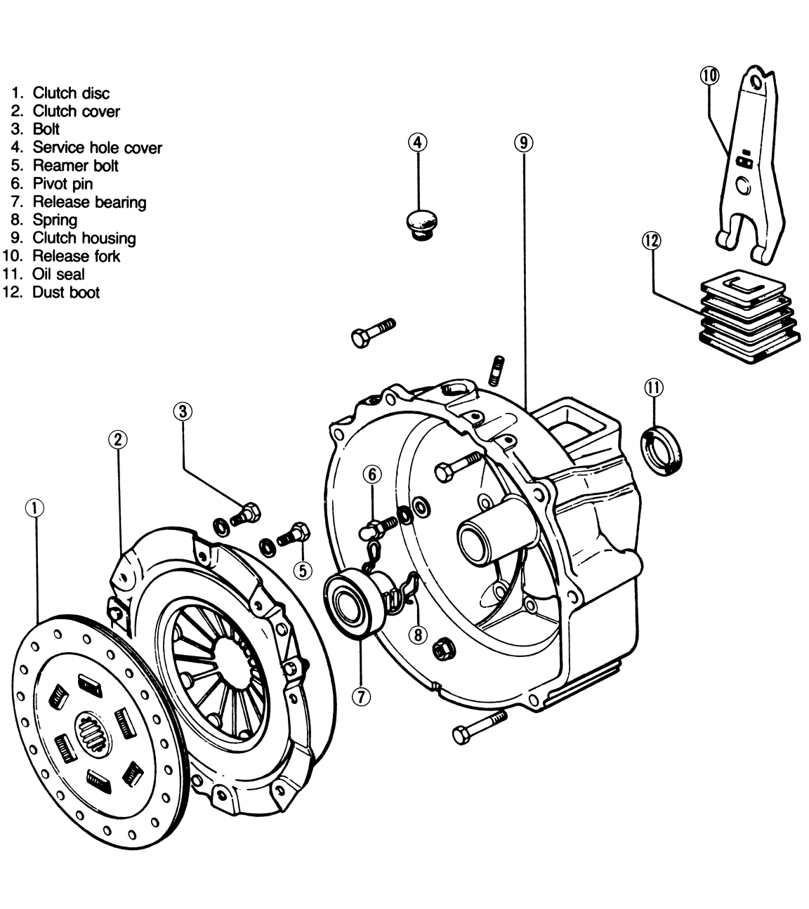
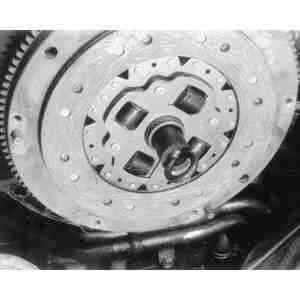
| Fig. 1: 1972–75 piston engine clutch assembly
|
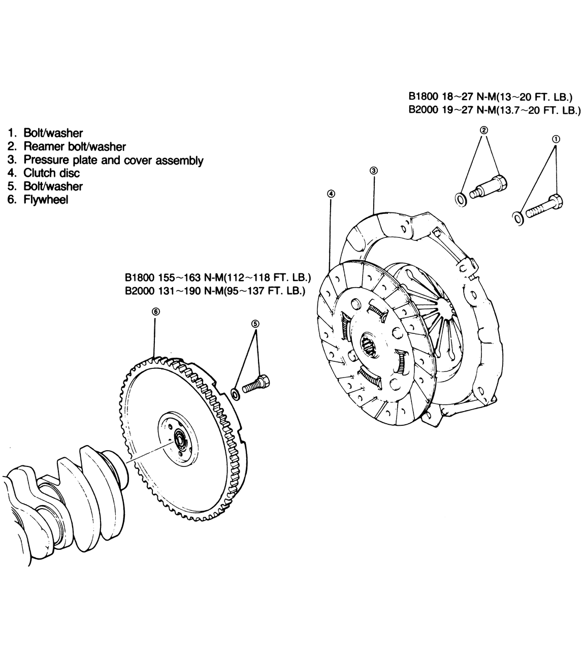
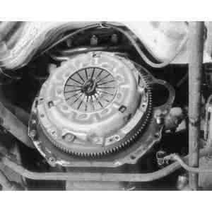
| Fig. 2: 1976–84 piston engine clutch assembly
|
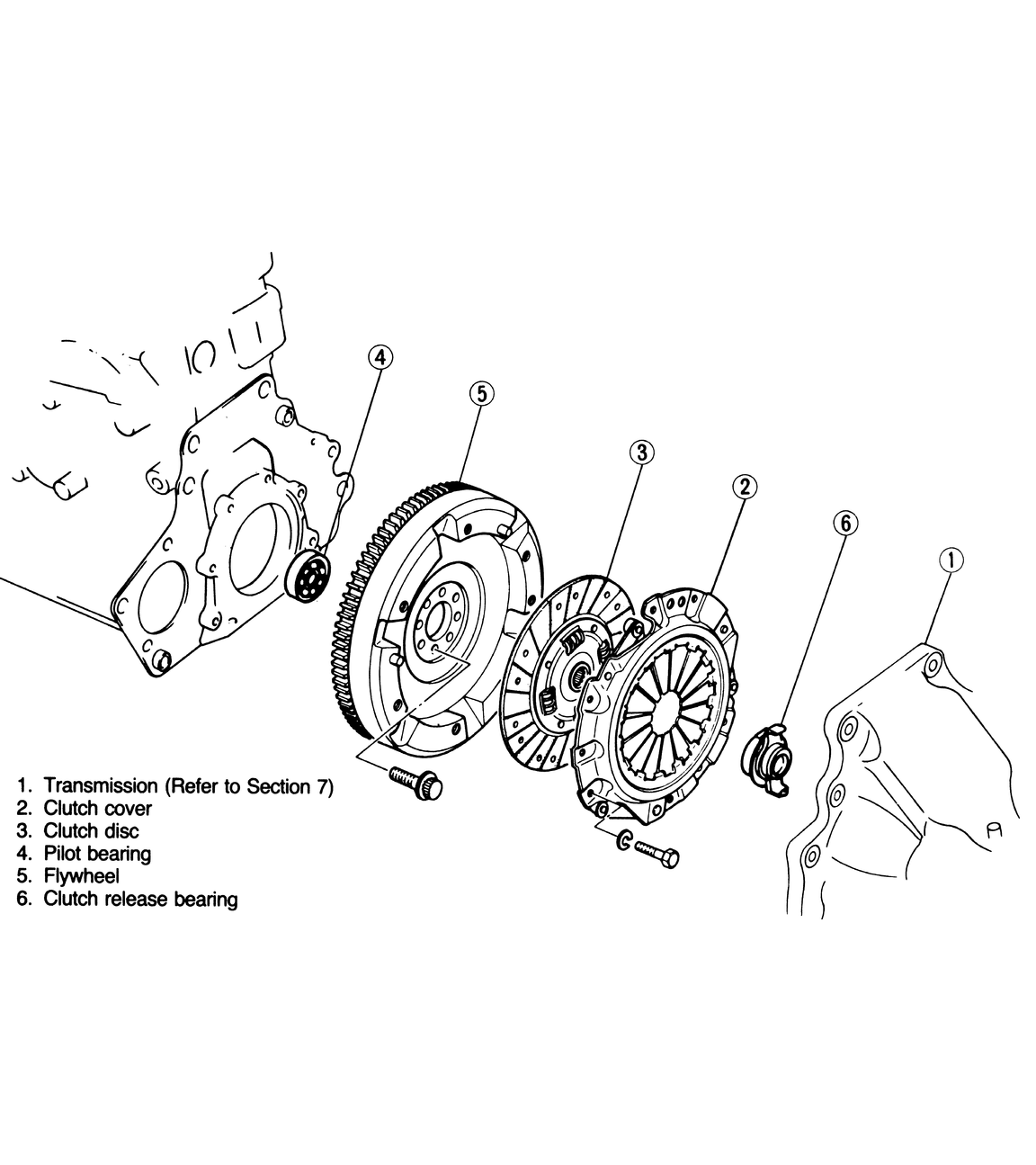
| Fig. 3: View of the 1986 clutch assembly
|
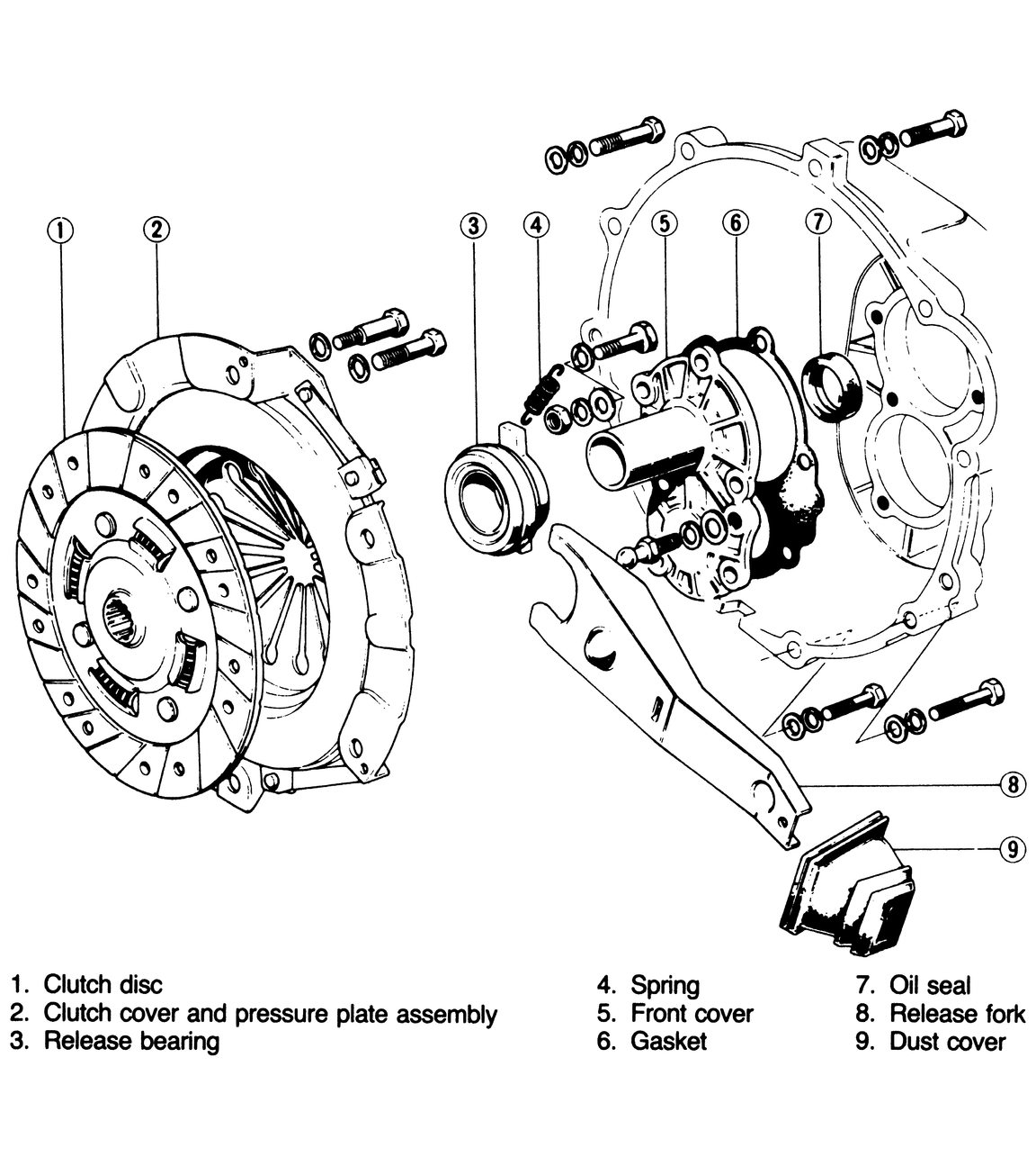
| Fig. 4: Rotary engine clutch assembly
|
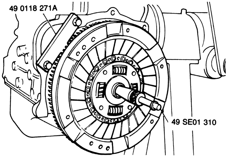
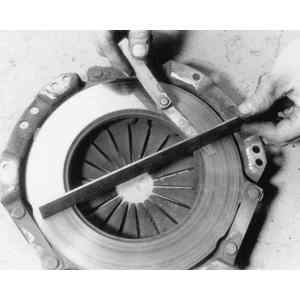
| Fig. 5: Clutch aligning tool and flywheel holding tool
in place
|
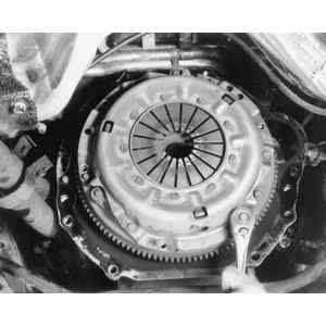
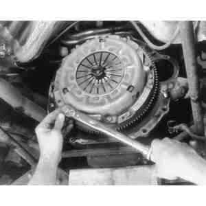
| Fig. 6: Loosen and remove the clutch and pressure plate
bolts evenly, a little at a time . . .
|
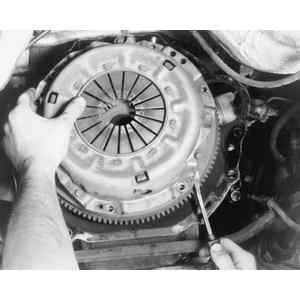
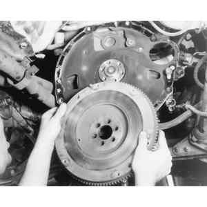
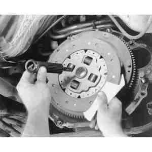
| Fig. 7: Removing the clutch and pressure plate assembly
|
| Fig. 8: . . . then carefully remove the clutch and
pressure plate assembly from the flywheel
|
| Fig. 9: View of the flywheel once the clutch assembly
is removed
|
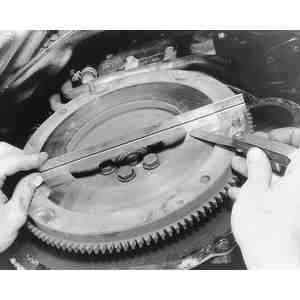
| Fig. 10: Check across the flywheel surface, it should
be flat
|
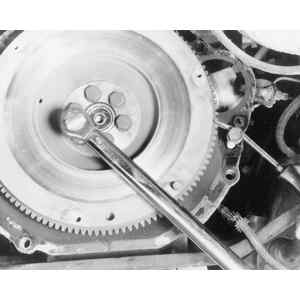
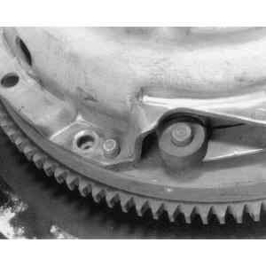
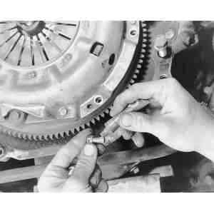
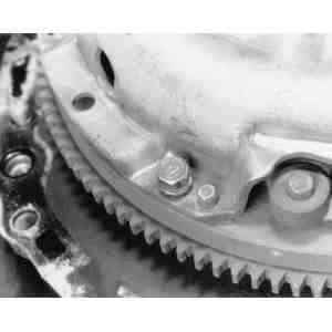
| Fig. 11: If necessary, lock the flywheel in place and
remove the retaining bolts . . .
|
| Fig. 12: . . . then remove the flywheel from the crankshaft
in order replace it or have it machined
|
| Fig. 13: Upon installation, it is usually a good idea
to apply a thread-locking compound to the flywheel bolts
|
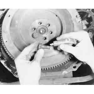
| Fig. 14: Check the pressure plate for excessive wear
|
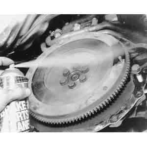
| Fig. 15: Be sure that the flywheel surface is clean,
before installing the clutch
|
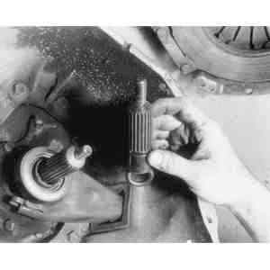
| Fig. 16: Typical clutch alignment tool, note how the
splines match the transmission's input shaft
|
| Fig. 17: Install a clutch alignment arbor, to align
the clutch assembly during installation
|
| Fig. 18: Clutch plate installed with the arbor in place
|
| Fig. 19: Clutch plate and pressure plate installed
with the alignment arbor in place
|
| Fig. 20: Pressure plate-to-flywheel bolt holes should
align
|
| Fig. 21: You may want to use a thread locking compound
on the clutch assembly bolts
|
| Fig. 22: Install the clutch assembly bolts and tighten
in steps, using an X pattern
|
| Fig. 23: Be sure to use a torque wrench to tighten
all bolts
|
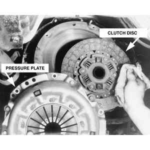
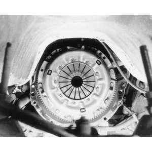
| Fig. 24: View of the clutch and pressure plate assembly
|
CAUTION
The clutch driven disc may contain asbestos, which has been determined to
be a cancer causing agent. Never clean clutch surfaces with compressed air!
Avoid inhaling any dust from any clutch surface! When cleaning clutch surfaces,
use a commercially available brake cleaning fluid.