| Fig. 1: Exploded view of the torsion bar removal/installation
for 1986 trucks
|
| Fig. 2: Matchmark all components — anchor
arm-to-torsion bar shown
|
| Fig. 3: Matchmarking the anchor bolt prior to removal
for ease of re-assembly
|
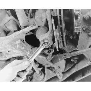
| Fig. 4: Measuring ball joint preload
|
| Fig. 5: Removing and installing the ball joint dust boot — always
inspect all parts for wear and visible damage, and replace as needed
|
| Fig. 6: Installing the ball joint on the lower arm
|
| Fig. 7: Torque plate installation
|
| Fig. 8: Connecting the tension rod and stabilizer link
|
| Fig. 9: Connecting the torsion bar to the torque plate — align
the matchmarks made prior to disassembly
|
| Fig. 10: Anchor arm positioning for installation when
matchmarks aren't present
|
| Fig. 11: Measuring points for ride height
|
| Fig. 12: After removing the cotter pin, loosen the lower
ball joint-to-control arm nut — do NOT remove the nut
unless the lower control arm is safely supported
|
NOTE: Special tools are necessary for this procedure.
NOTE: Don't change the position of the double nut at the rear of the tension rod bushing, since it would affect caster.
NOTE: If, for some reason, you didn't matchmark the torsion bar anchor bolt, or the matchmarks were lost, or you're installing a new, unmarked torsion bar, here's a procedure to help you attain the correct ride height: