| Fig. 1: Exploded view of the early 1972 B1600 master
cylinder
|
| Fig. 2: Exploded view of the late 1972 through 1975 B1600
master cylinder
|
| Fig. 3: Exploded view of the rotary pick-up master cylinder
|
| Fig. 4: Exploded view of the 1976 master cylinder
|
| Fig. 5: Exploded view of the 1977–78 master cylinder
|
| Fig. 6: Exploded view of the 1979–80 master cylinder
|
| Fig. 7: Exploded view of the 1981 master cylinder
|
| Fig. 8: Exploded view of the 1982–84 B2000 and
B2200 master cylinder
|
| Fig. 9: Diagram of the guide pin and its usage
|
| Fig. 10: Exploded view of the 1986 master cylinder
|
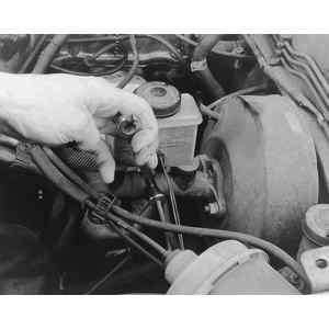
| Fig. 11: To remove the master cylinder, remove the brake
lines connected to the master cylinder . . .
|
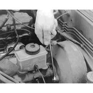
| Fig. 12: . . . then unbolt the master cylinder attaching
nuts
|
| Fig. 13: On 1986 models, also unplug the fluid level
sensor wire
|
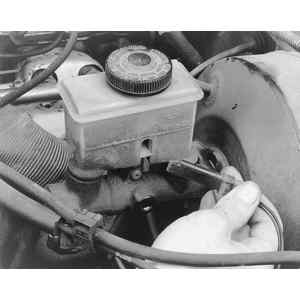
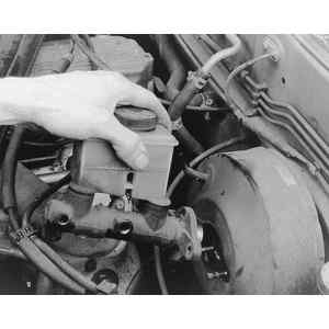
| Fig. 14: Finally lift the master cylinder off the mounting
studs
|