The valve lash on all engines is kept in adjustment hydraulically. No adjustment
is necessary, or possible.
These engines use solid cam followers with a removable adjustment shim. The
valve lash clearance is measured with the original shim installed and checked
against the specification. If adjustment is necessary, the original shim is
removed, and a thicker or thinner shim is installed to obtain the proper clearance.
Special tools are required in order to adjust the shim without removing the
camshaft.
NOTE: With the engine cold, standard valve clearance is 0.010-0.012
in. (0.25-0.31mm) on intake and exhaust sides.
- Remove the cylinder head cover.
- Measure the valve clearance by turning the crankshaft clockwise until the
No. 1 piston is at TDC.
| Fig. 1: Ensure that the cam lobe faces away from
the follower when checking the valve clearance
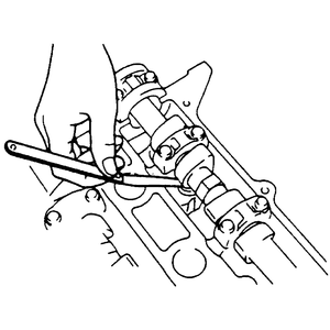
|
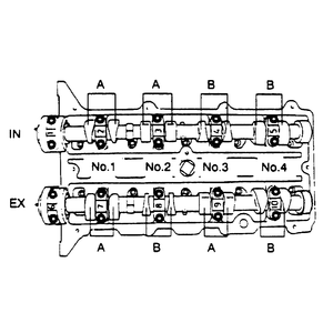
- Measure the valve clearance at A. If the clearance exceeds specifications,
replace the adjustment shim.
| Fig. 2: Mazda 4-cylinder engines valve clearance
checking positions
|
- Turn the crankshaft clockwise 360 degrees until the No. 4 piston is at TDC.
Measure the valve clearance at B. If the clearance exceeds specifications,
replace the adjustment shim.
- Repeat this procedure for all the camshafts.
- Turn the crankshaft clockwise until the cam on the camshaft requiring the
adjustment is positioned straight up.
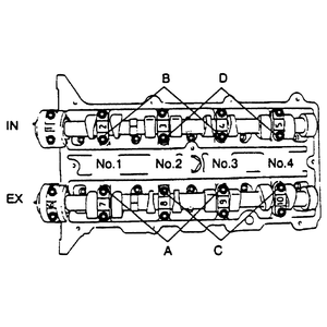
| Fig. 3: Mazda 4-cylinder engines cam cap bolt removal
positions — refer to text
|
- Remove the camshaft cap bolts as follows:
- For exhaust side No. 1, 2, and 3 cylinder adjustment shim removal use A.
- For intake side No. 1, 2, and 3 cylinder adjustment shim removal use B.
- For exhaust side No. 2, 3, and 4 cylinder adjustment shim removal use C.
- For intake side No. 2, 3, and 4 cylinder adjustment shim removal use D.
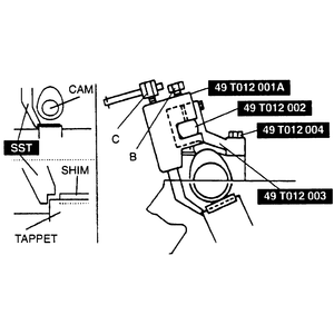
- Install special tools 49-T012-002 and 003, using the camshaft cap bolt holes.
Torque the bolts to 100-125 inch lbs. (11-14 Nm).
- Align the mark on the 49-T012-002 (shaft) with the mark on the 49-T012-003
(clamp). Tighten special tool 49-T012-004 (bolt) to secure the shaft.
- Position special tool 49-T012-001A toward the center of the cylinder head,
and mount it on the shaft where the adjustment shim needs replacement.
- Position the notch of the tappet to allow a small pry tool to be inserted.
| Fig. 4: Mount the tappet depressor tool onto the
shaft above the tappet which needs adjustment
|
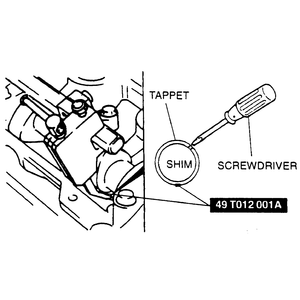
| Fig. 5: With the tappet depressed, use a small prytool
to remove the adjustment shim
|
- Set the special tool on the tappet by its notch. Tighten the mounting bolt B securing
it on the shaft.
- Tighten bolt C, and press down the tappet.
- Using a small pry tool, pry the adjustment shim upwards through the notch
on the tappet. Remove the shim with a magnet.
- Select and install the proper adjustment shim. Loosen bolt C to
allow the tappet to move up, and loosen bolt B to remove
special tool 49-T012-001A.
- Remove special tools 49-T012-002, 003 and 004, and tighten the camshaft
cap bolts to 100-125 inch lbs. (11-14 Nm).
- Repeat the procedure for all necessary adjustment shims. Check the valve
clearance.
NOTE: With the engine cold, standard valve clearance is 0.011-0.012
in. (0.27-0.31mm) on intake and exhaust sides.
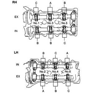
- Measure the valve clearance by turning the crankshaft clockwise until the
No. 1 piston is at TDC.
- Measure the valve clearance at A. Turn the crankshaft clockwise
240 degrees until the No. 3 piston is at TDC. Measure the valve clearance
at B. Turn the crankshaft clockwise 240 degrees until the No.
5 piston is at TDC. Measure the valve clearance at C.
| Fig. 6: Mazda 6-cylinder engine valve clearance checking
positions
|
NOTE: If the valve clearance exceeds the standard, replace
the adjustment shim.
- Turn the crankshaft clockwise until the cam, on the camshaft requiring the
adjustment shim replacement, is positioned straight up.
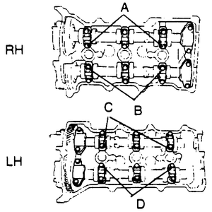
| Fig. 7: Mazda 6-cylinder engines cam cap bolt removal
positions — refer to text
|
- Remove the camshaft cap bolts as follows:
- For right-hand (RH) exhaust side shim removal use 1.
- For right-hand (RH) intake side shim removal use 2.
- For left-hand (LH) intake side shim removal use 3.
- For left-hand (LH) exhaust side shim removal use 4.
- Install special tools 49-T012-002 and 003, using the camshaft cap bolt holes.
- Align the mark on the 49-T012-002 (shaft) with the mark on the 49-T012-003
(clamp).
- Position special tool 49-T012-001 toward the center of the cylinder head,
and mount it on the shaft where the adjustment shim needs replacement.
- Position the notch of the tappet to allow a small pry tool to be inserted.
- Set the special tool on the tappet by its notch. Tighten the mounting bolt B securing
it on the shaft.
- Tighten bolt C, and press down the tappet.
- Using a small pry tool, pry the adjustment shim upwards through the notch
on the tappet. Remove the shim with a magnet.
- Select and install the proper adjustment shim. Loosen bolt C to
allow the tappet to move up, and loosen bolt B to remove special tool 49-T012-001.
- Remove special tools 49-T012-002, 003 and 004, and tighten the camshaft
cap bolts to 100-125 inch lbs. (11-14 Nm).
- Repeat the procedure for all necessary adjustment shims. Check the valve
clearance.


