Previous Next

Ignition Coil

IGNITION COIL RESISTANCE TEST

External Coils
  1. Disconnect the distributor wire from the coil.
  2. Disconnect the electrical connector from the coil.
  3. Check the resistance of the ignition coil primary by connecting an ohmmeter to both electrical terminals on the coil.

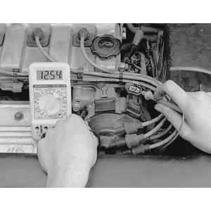
    Fig. 1: Connect an ohmmeter on both terminals of the ignition coil and measure the primary resistance

  4. Check the resistance of the ignition coil secondary windings by connecting an ohmmeter to coil positive terminal and the coil-to-distributor wire tower terminal.

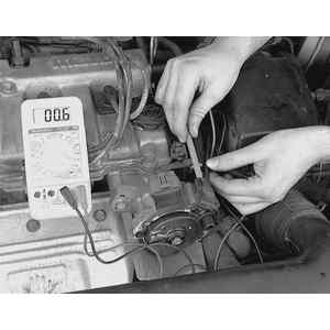
    Fig. 2: Connect an ohmmeter on to the positive terminal of the ignition coil and the coil wire tower to check the secondary resistance

  5. The resistance for all coils, except on 2.2L engines, should be as follows:
    1. Primary coil winding — 0.81–0.99 ohms.
    2. Secondary coil winding — 10–16 kilo ohms.
  6. The resistance for the coil on 2.2L engines, should be as follows:
    1. Primary coil winding (turbo) — 0.72–0.88 ohms.
    2. Primary coil winding (non-turbo) — 0.77–0.95 ohms.
    3. Secondary coil winding — 10.3–13.9 kilo-ohms.
  7. If the ignition coil resistance is not within specifications, replace the ignition coil.
  8. If the ignition coil is within the specified limits, connect a voltmeter to the ignition coil wire harness connectors positive terminal and a ground. Turn the ignition on and verify that you have battery voltage at the connector.
  9. If voltage is present, perform a spark test.
  10. If voltage is not present, check the wire harness and fuses for shorts or breaks.

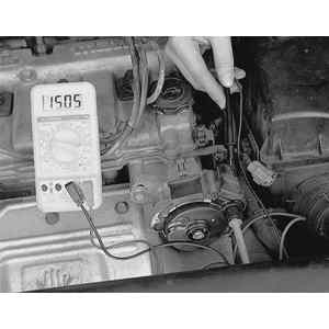
    Fig. 3: Use a voltmeter in the ignition coil wire harness connector positive terminal to check for voltage to the coil

Integral with Distributor Coil
  1. Disconnect the distributor wire from the coil.
  2. Disconnect the 3 pin electrical connector from the coil.
  3. Use an ohmmeter and check the resistance of the ignition coil primary winding. Connect the ohmmeter to the two outside terminals on the distributor (A and C). Terminal A is the closest terminal to the 6-pin connector, terminal B is in the middle and terminal C is the last terminal.

    Fig. 4: Connect an ohmmeter on terminals A and C of the ignition coil distributor connector and measure the primary resistance

  4. The resistance should be 0.58–0.86 ohms.
  5. If the resistance is not within specifications, replace the distributor assembly. If the resistance is within specifications, proceed with step 6.

    Fig. 5: Connect an ohmmeter to the positive terminal of the ignition coil connector and the coil tower to check the secondary resistance

  6. Remove the distributor cap and use an ohmmeter to measure the secondary coil resistance. Connect the ohmmeter to terminal C and the coil tower connector.
  7. The resistance should be 11.5–18.5 ohms.
  8. If the ignition coil resistance is not within specifications, replace the distributor.
  9. If the ignition coil is within the specified limits, connect a voltmeter to the ignition coil wire harness connectors positive terminal (terminal C) and a ground. Turn the ignition on and verify that you have battery voltage at the connector.
  10. If voltage is present, perform a spark test.
  11. If voltage is not present, check the wire harness and fuses for shorts or breaks.

Previous Next