Previous Next

REMOVAL & INSTALLATION

Fig. 1: Exploded view of a typical side mounted starter assembly

Fig. 2: Exploded view of a typical top mounted (mostly V6 engines with automatic transmissions) starter assembly

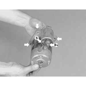
Fig. 3: View of the starter motor mounting bolt locations and electrical terminal identification

1995–98 Protege Models
  1. Disconnect the negative battery cable.
  2. Remove the air cleaner.
  3. Raise and safely support the vehicle.
  4. Disconnect the catalytic converter pipe from the front pipe.
  5. Remove the intake manifold support bracket bolts and the bracket.
  6. Disconnect the electrical connectors from the starter and solenoid.
  7. Remove the starter mounting bolts, and remove the starter.

    To install:

  8. Position the starter and loosely tighten the lower starter mounting bolt.
  9. Connect the electrical connectors to the starter solenoid and the starter.
  10. Install the intake manifold support bracket bolts and the bracket. Tighten the bolts to 28–38 ft. lbs. (38–51 Nm).
  11. Install the upper starter mounting bolts. Tighten all starter mounting bolts to 24–33 ft. lbs. (32–46 Nm). The upper mounting bolts must be tightened first.
  12. Connect the catalytic converter pipe to the front pipe. Tighten the bolts to 28–38 ft. lbs. (38–51 Nm).
  13. Lower the vehicle.
  14. Install the air cleaner.
  15. Connect the negative battery cable.
MX-3 with 1.8L Engine
  1. Disconnect the negative battery cable.
  2. Remove the nuts and the upper strut bar from between the strut towers.
  3. Remove the intake air hose from between the air cleaner and throttle body.
  4. Label and disconnect the wiring from the starter.
  5. Remove the mounting bolts and remove the starter.

    To install:

  6. Install the starter and install the mounting bolts. Tighten the bolts to 38 ft. lbs. (52 Nm).
  7. Connect the wiring to the starter.
  8. Install the intake air hose between the air cleaner and throttle body.
  9. Install the upper strut bar to between the strut towers.
  10. Connect the negative battery cable.
1993–98 626/MX-6/Probe Models
2.0L ENGINE
  1. Disconnect the negative battery cable.
  2. Remove the fresh air duct and resonance chamber.

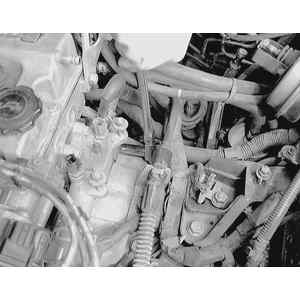
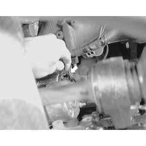
    Fig. 4: To remove the starter motor, first remove any obstructing components, then loosen the upper starter motor attaching bolts

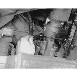
    Fig. 5: Remove both upper bolts before going under the vehicle to finish the removal procedure

  3. Label and disconnect the electrical connectors and remove the air cleaner assembly.
  4. Remove the intake manifold bracket.

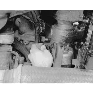
    Fig. 6: Raise and safely support the front of the vehicle, then label and detach any plug-on wire connectors

    Fig. 7: Using the proper size socket or wrench, remove the battery positive wire retaining nut . . .

    Fig. 8: . . . and the wire terminal from the starter

  5. Label and disconnect the wiring at the starter.
  6. Remove the starter mounting bolts and remove the starter.

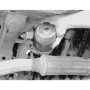
    Fig. 9: Remove the lower starter motor mounting bolt and carefully lower the starter and remove it from the vehicle

  7. Installation is the reverse of the removal procedure. Tighten the starter mounting bolts to 33 ft. lbs. (46 Nm) and the intake manifold bracket bolts to 38 ft. lbs. (51 Nm).
2.5L ENGINE
  1. Disconnect the negative battery cable.
  2. Remove the fresh air duct. Disconnect the electrical connector and remove the air cleaner assembly.
  3. If equipped with automatic transaxle, proceed as follows:
    1. Relieve the fuel system pressure. Drain the cooling system.
    2. Disconnect the accelerator cable from the throttle body. Label and disconnect the electrical connectors, vacuum hoses and coolant hoses from the throttle body.
    3. Remove the throttle body.
    4. Disconnect and plug the fuel supply and return lines.
    5. Disconnect the transaxle selector cable from the transaxle and remove the cable bracket.
    6. Remove the starter bracket.
  4. Label and disconnect the wiring at the starter.
  5. Remove the starter mounting bolts and remove the starter.
  6. Installation is the reverse of the removal procedure. Tighten the starter mounting bolts to 38 ft. lbs. (51 Nm).
Millenia Models
2.3L ENGINE
  1. Disconnect the negative battery cable.
  2. Remove the charge air cooler duct.
  3. Remove the battery clamp, box, and battery. Remove the battery tray.
  4. Remove the rear charge air cooler.
  5. Remove the bolt from the pipe bracket and remove the bracket.
  6. Remove the S-terminal wire from the starter solenoid.
  7. Remove the nut and the B-terminal wire from the starter solenoid.
  8. Remove the starter mounting bolts and remove the starter.

    To install:

  9. Position the starter and tighten the starter mounting bolts to 24–33 ft. lbs. (32–46 Nm).
  10. Install the B-terminal wire and nut. Tighten the nut to 12–16 ft. lbs. (16–22 Nm).
  11. Install the S-terminal wire to the solenoid.
  12. Position the pipe bracket and install the bolt. Tighten the bolt to 14–18 ft. lbs. (19–25 Nm).
  13. Install the rear charge air cooler, using new O-rings. Tighten the nuts to 14–18 ft. lbs. (19–25 Nm).
  14. Install the battery tray. Install the battery, box, and clamp.
  15. Install the charge air cooler duct.
  16. Connect the negative battery cable.
2.5L ENGINE
  1. Disconnect the negative battery cable.
  2. Remove the battery clamp, box, and battery. Remove the battery tray.
  3. Remove the shift cable from the selector lever using a screwdriver or suitable tool.
  4. Squeeze the lock tabs on the shift cable and remove the cable from the bracket.
  5. Disconnect the electrical connectors from the starter solenoid.
  6. Position the wiring harness out of the way.
  7. Remove the two selector cable bracket mounting bolts and the bracket.
  8. Remove the two nuts and the bolt from the starter bracket and remove the bracket.
  9. Remove the S-terminal wire from the starter solenoid.
  10. Remove the nut and the B-terminal wire from the starter solenoid.
  11. Remove the starter mounting bolts and remove the starter.

    To install:

  12. Position the starter and tighten the starter mounting bolts to 24–33 ft. lbs. (32–46 Nm).
  13. Install the B-terminal wire and nut. Tighten the nut to 12–16 ft. lbs. (16–22 Nm).
  14. Install the S-terminal wire to the solenoid.
  15. Position the starter bracket and install the bolt and nuts.
  16. Install the selector cable bracket and tighten the bolts to 5–7 ft. lbs. (7–9 Nm).
  17. Connect the electrical connectors to the starter solenoid.
  18. Install the shift cable into the cable bracket and into the selector lever.
  19. Install the battery tray. Install the battery, box, and clamp.
  20. Connect the negative battery cable.
Except MX-3 (w/1.8L), 1993–98 626/MX-6/Probe, 1995–98 Protege and Millenia
  1. Disconnect the negative battery cable. On 323/Protege and MX-3 1.6L engine, disconnect the positive battery cable and remove the battery and battery tray.
  2. Raise and safely support the vehicle. Remove the engine under cover.
  3. On 323/Protege, MX-3 with 1.6L engine and MX-6/626 2.2L engine, remove the intake manifold bracket.
  4. On 323 with 4WD, remove the differential lock assembly as follows:
    1. Remove the retaining bolt.
    2. Turn the differential lock shift rod 90 degrees clockwise with a flat-bladed tool.
    3. Remove the differential lock assembly.
  5. Remove the starter bracket, if equipped.
  6. Label and disconnect the wiring from the starter.
  7. Remove the starter mounting bolts and remove the starter.

    To install:

  8. Install the starter and install the mounting bolts.
  9. Tighten the starter mounting bolts to 34 ft. lbs. (46 Nm).
  10. Connect the wiring to the starter and install the bracket, if equipped.
  11. On 323 with 4WD install the differential lock assembly.
  12. On 323/Protege, MX-3 with 1.6L engine and MX-6/626 2.2L engine, install the intake manifold bracket.
  13. Install the engine under cover and lower the vehicle.
  14. Install the battery, if removed. Connect the negative battery cable.

Previous Next