Previous Next

Rocker Arm (Valve) Cover

REMOVAL & INSTALLATION

1.6L, 1.8L SOHC (except K8) and 2.2L Engines
  1. Disconnect the vent hose from the rocker arm cover.

    Fig. 1: Exploded view of the 1.6L, 1.8L SOHC (except K8) engine valve cover assembly — 2.2L engine is similar

  2. Remove the PCV valve from the rocker arm cover.
  3. Remove the spark plug wires from the wire clips.
  4. Remove the rocker arm cover retaining bolts and remove the rocker arm cover and gasket.

    To install:

  5. Clean all old gasket material from the rocker arm cover and the cylinder head.
  6. Install a new gasket onto the rocker arm cover.
  7. Apply silicone sealer around the groove of the cover.
  8. Install the rocker arm cover on the cylinder head with the retaining bolts. Tighten the bolts to 43–78 inch lbs. (5–9 Nm).
  9. Install the spark plug wires to the retaining clips and install the PCV valve. Connect the vent hose to the rocker arm cover.
  10. Start the engine and bring to normal operating temperature. Check for leaks.
1.5L, 1.8L DOHC (except K8) and 2.0L Engines
  1. As necessary, unbolt the power steering hose securing brackets from the valve cover. It may be necessary to remove the power steering pump in order to allow the hose enough range of motion to clear the valve cover.

    Fig. 2: Exploded view of the 1.5L engine valve cover assembly1.8L DOHC (except K8) and 2.0L engine is similar

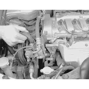
    Fig. 3: To remove the valve cover, first unbolt any components which are attached to the valve cover . . .

    Fig. 4: . . . and ensure that any components which may obstruct cover removal are positioned aside

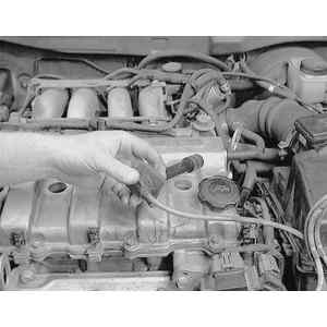
    Fig. 5: Next, label and remove the spark plug wires from the plugs

  2. Label and remove the spark plug wires from the plugs.
  3. Disconnect the vent hose from the cover.

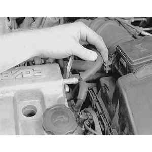
    Fig. 6: Also detach the PCV valve and vent hose (shown) from the valve cover

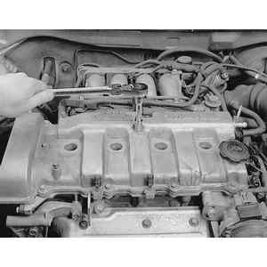
    Fig. 7: Loosen the valve cover retaining bolts evenly, over three steps . . .

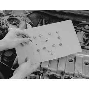
    Fig. 8: . . . then remove them. Keep the bolts in order as some of them are of differing lengths and must be returned to their original hole

    Fig. 9: Remove the valve cover. Some gentle tapping with a soft faced hammer may be necessary to break the seal

  4. Disconnect the PCV hose from the cover.
  5. Loosen the cover bolts evenly over three steps.
  6. Remove the valve cover bolts, keeping them in order. Some bolts are longer than others and should be returned to their original locations.
  7. Remove the cover from the engine.

    To install:

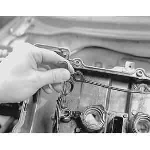
    Fig. 10: Remove the old gasket from the valve cover and discard it. Clean all gasket mating surfaces thoroughly

  8. Clean all old gasket material from the cover and the cylinder head.
  9. Install a new gasket onto the cover.

    Fig. 11: Apply sealer to any point on the cylinder head mating surface where the gasket must arch over a cam cap

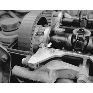
    Fig. 12: Close up example of a cam cap arch where sealer should be placed

  10. Apply silicone sealer to the shaded area of the cylinder head as shown in the figure.

    Fig. 13: Valve cover bolt tightening sequence for the 1.5L engine

    Fig. 14: Valve cover bolt tightening sequence for the 1.8L and 2.0L engines

  11. Install the cover on the cylinder head with the retaining bolts. Tighten the bolts in the order shown in fig39 to 52–69 inch lbs. (6–8 Nm).
  12. Install the spark plug wires to the spark plugs. Connect the vent hose and the PCV hose to the cover.
  13. Start the engine and bring to normal operating temperature. Check for leaks.
1.8L DOHC (K8), 2.3L and 2.5L Engine
  1. Disconnect the negative battery cable.
  2. On the 1.8L and 2.5L engines, remove the intake manifold stay bracket from the engine.
  3. Disconnect the vent hoses from the intake manifold and from the cover assembly.

    Fig. 15: To remove the valve cover on V6 engines, detach the spark plug wires from the plugs, and if necessary, remove the intake manifold

  4. Remove the spark plug wires from the spark plugs, make a note of plug wire original location.
  5. On 2.3L engines and for rear valve cover removal on the 1.8L and 2.5L engines perform the following:
    1. Remove the intake manifold assembly from the engine.

      Fig. 16: Exploded view of the valve cover assemblies on the V6 engines

  6. Remove the ventilation pipe attaching bolts and disconnect the pipe from the front cover.
  7. Remove the cover bolts and remove the cover assembly.

    To install:

  8. Clean all old gasket material from the rocker arm cover and the cylinder head.
  9. Install a new gasket onto the cover.
  10. Apply silicone sealer to the cylinder head perimeter.

    Fig. 17: Mazda V6 engines valve cover bolt tightening sequence for right-hand covers

    Fig. 18: Mazda V6 engines valve cover bolt tightening sequence for left-hand covers

  11. Install the cover assembly and the bolts and tighten in the sequence shown over three steps to 43–78 inch lbs. (4.9–8.8 Nm).
  12. Install the ventilation pipe to the front cover assembly and tighten the bolts to 69–95 inch lbs. (7.8–11 Nm).
  13. If removed, install a new gasket to the intake manifold assembly and install it to the engine. Loosely tighten the bolts and nuts.
  14. On the 1.8L and 2.5L engines, install the intake manifold stay and tighten the bolts to 14–19 ft. lbs. (19–25 Nm).
  15. If necessary, tighten the intake manifold nuts and bolts over three stages to the proper specification.
  16. Connect the vent hoses and connect the negative battery cable.
  17. Start the engine and inspect for leaks.

Previous Next