Previous Next

TESTING

Fig. 1: Throttle position sensor test connections for 3-wire sensors

Fig. 2: Throttle position sensor test connections for 4-wire sensors

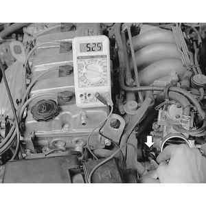
Fig. 3: When measuring the resistance (arrow), open and close the throttle and check for smooth changes in resistance

MX-3 with 1.6L SOHC Engine, 323 and Protege
MANUAL TRANSAXLE
  1. Detach the connector from the throttle position sensor.
  2. Connect an ohmmeter between terminals IDL and E.
  3. Insert a 0.004 in. (0.1mm) feeler gauge between the throttle stop screw and stop lever.
  4. Verify there is continuity between terminals IDL and E.
  5. Then replace the feeler gauge with a 0.039 in. (1.0mm) feeler gauge, verify there is no continuity between terminals IDL and E.
  6. Then open the throttle wide and verify there is no continuity again between terminals IDL and E.
  7. Next, connect the ohmmeter between terminals POW and E.
  8. Insert a 0.004 in. (0.1mm) feeler gauge between the throttle stop screw and stop lever.
  9. Verify there is no continuity between terminals POW and E.
  10. Then replace the feeler gauge with 0.039 in. (1.0mm), verify there is no continuity between terminals POW andE.
  11. Then open the throttle wide and verify there is continuity between terminals POW and E.
  12. If not as specified, adjust or replace the throttle sensor.
AUTOMATIC TRANSAXLE
  1. Detach the connector from the throttle position sensor.
  2. Connect an ohmmeter between terminals IDL and E.
  3. Insert a 0.004 in. (0.1mm) feeler gauge between the throttle stop screw and stop lever.
  4. Verify there is continuity between terminals IDL and E.
  5. Insert a 0.024 in. (0.6mm) feeler gauge between the throttle stop screw and stop lever.
  6. Verify there is continuity no between terminals IDL and E.
  7. Connect an ohmmeter to the throttle sensor terminals Vt and E.
  8. Verify that resistance increases as throttle valve opening increase.
  9. With throttle valve fully closed the resistance should be below 1 kilohm and as throttle valve is fully opened resistance should increase to approximately 5 kohms.
  10. If not as specified, adjust or replace the throttle sensor.
626 and MX-6 with 2.2L Engine
  1. Remove the air hose from the throttle body.
  2. Detach the 3-pin throttle sensor connector.
  3. Connect the 49-G018-901 testing harness or equivalent, between the throttle sensor and the wiring harness.
  4. Turn the ignition switch ON.
  5. Verify the throttle valve is fully closed.
  6. Measure the voltage at the black and the red wires of the testing harness using a precision voltmeter with a scale of 0.01 volts, the voltage at the black wire should be approximately 0 volts and the voltage at the red wire should be 4.5–5.5 volts.
  7. If the voltage reading is not as specified, check the battery voltage and wiring harness, if these are okay, replace the engine control unit.
  8. Record the red wire voltage.
  9. Measure the voltage of the blue wire, verify that the blue wire voltage is within specification according to the red wire voltage. For example; if the red wire voltage reading is 4.50–4.59 volts, then the blue wire voltage reading would have to be within 0.37–0.54 volts.
  10. Hold the throttle valve fully open.
  11. Measure the blue wire voltage, verify that the blue wire voltage is within specification according to that of the red wire voltage. For example; if the red wire voltage reading is 4.50–4.59 volts, then the blue wire voltage reading would have to be within 3.58–4.23 volts.
  12. Check that blue wire voltage increases smoothly when opening the throttle valve from closed to fully open.
  13. If the throttle sensor does not perform as specified, adjust or replace the sensor.
  14. Turn the ignition OFF.
  15. Detach the testing harness and reattach the throttle sensor connector.
  16. Disconnect the negative battery terminal and depress the brake pedal for at least 5 seconds to eliminate the control unit malfunction memory.
MX-3 with 1.6L DOHC and 626/MX-6/Probe with 2.0L Engine
MANUAL TRANSAXLE
  1. Detach the connector from the throttle position sensor.
  2. Connect an ohmmeter between terminals IDL and E.
  3. Insert a 0.004 in. (0.1mm) feeler gauge between the throttle stop screw and stop lever.
  4. Verify there is continuity between terminals IDL and E.
  5. Then replace the feeler gauge with a 0.027 in. (0.7mm) feeler gauge, verify there is no continuity between terminals IDL and E
  6. Then open the throttle wide and verify there is no continuity again between terminals IDL and E.
  7. Next, connect the ohmmeter between terminals POW and E.
  8. Insert a 0.004 in. (0.1mm) feeler gauge between the throttle stop screw and stop lever.
  9. Verify there is no continuity between terminals POW and E.
  10. Then replace the feeler gauge with 0.027 in (0.7mm), verify there is no continuity between terminals POW and E.
  11. Then open the throttle wide and verify there is continuity between terminals POW and E.
  12. If not as specified, adjust or replace the throttle
AUTOMATIC TRANSAXLE
  1. Detach the connector from the throttle position sensor.
  2. Connect an ohmmeter between the terminals IDL and E.
  3. Insert a 0.004 in. (0.1mm) feeler gauge between the throttle stop screw and stop lever.
  4. Verify there is continuity between terminals IDL and E.
  5. Insert a 0.024 in. (0.6mm) feeler gauge between the throttle stop screw and stop lever.
  6. Verify there is no continuity between terminals IDL and E.
  7. Connect an ohmmeter to the throttle sensor terminals Vt and E.
  8. Verify that resistance increases as throttle valve opening increase.
  9. With throttle valve fully closed the resistance should be below 1 kilohm and as throttle valve is fully opened resistance should increase to approximately 5 kohms.
  10. If not as specified, adjust or replace the throttle sensor.
Millenia, MX-3 with 1.8L (K8) and 626/MX-6/Probe with 2.5L Engines
  1. Detach the connector from the throttle position sensor.
  2. Connect an ohmmeter between terminals IDL and GND.
  3. Rotate the throttle linkage by hand. With the throttle valve fully closed, the ohmmeter should read 0.1–1.1 volts.
  4. With the throttle valve fully open, the ohmmeter should read 3.1–4.4 volts.
  5. If not as specified, adjust or replace the throttle position sensor.

Previous Next