Previous Next

Fuel Injectors

REMOVAL & INSTALLATION

Fig. 1: Exploded view of the typical 4-cylinder engine fuel injector and distributor assembly

Fig. 2: Exploded view of the typical 6-cylinder engine fuel injector and distributor assemblies

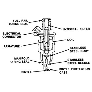
Fig. 3:Cross-sectional view of a typical MFI fuel injector

MX-3 with 4-Cylinder Engine and 1990–94 323, Protege
  1. Relieve the fuel system pressure.
  2. Disconnect the negative battery cable.
  3. Detach the electrical connectors at the injectors.
  4. Remove the fuel injector harness from the fuel delivery pipe.
  5. Remove the delivery pipe bolt(s) and remove the delivery pipe with the injectors and the pressure regulator.
  6. Separate the injectors, grommets and the insulators from the delivery pipe assembly.

    To install:

  7. Replace the fuel injector O-rings and apply a small amount of clean engine oil to the O-rings before installation.
  8. Replace the fuel injector insulator seals.
  9. Install the injectors to the delivery pipe and install the assembly to the engine. Tighten the delivery pipe bolt to 14–18 ft. lbs. (19–25 Nm).
  10. Install the injector harness to the fuel delivery pipe and connect the injector wiring.
  11. Connect the negative battery cable.
1995–97 Protege
  1. Relieve the fuel system pressure, and disconnect the negative battery cable.
  2. Disconnect the throttle and accelerator cables. Remove the cable bracket.
  3. Label and disconnect the fuel injector wiring harness.
  4. Disconnect and plug the fuel lines at the fuel distributor.
  5. Disconnect the vacuum hose from the fuel pressure regulator.
  6. Remove the fuel line mounting bracket bolt.
  7. Remove the fuel distributor mounting bolts, spacers, insulators and the fuel distributor, with the injectors attached.
  8. Remove the fuel injectors, grommets and O-rings from the fuel distributor. Remove the O-rings from the fuel injectors.

    To install:

  9. Apply a small amount of clean engine oil to new O-rings and install them and the grommets on the fuel injectors.
  10. Install the insulators and injectors on the intake manifold.
  11. Install the grommets and the fuel distributor onto the injectors.
  12. Install the fuel distributor attaching bolts and tighten to 14–18 ft. lbs. (19–25 Nm).
  13. Connect the vacuum hose to the fuel pressure regulator and the fuel lines to the fuel distributor.
  14. Install the fuel line mounting bracket, and tighten the bolt to 70–95 inch lbs. (8–11 Nm).
  15. Connect the fuel injector wiring harness.
  16. Install the cable bracket, and tighten the bolt to 70–95 inch lbs. (8–11 Nm). Connect and adjust the throttle and accelerator cables.
  17. Connect the negative battery cable and turn the ignition switch ON to pressurize the fuel system. Check for leaks and correct as necessary, before starting the engine.
626/MX-6/Probe with 4-Cylinder Engines
2.0L ENGINE
  1. Properly relieve the fuel system pressure.

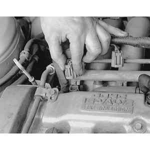
    Fig. 4: To remove the fuel injectors, first label and detach the injector wire harness connectors

  2. Disconnect the negative battery cable.
  3. If necessary, remove the air intake piping near the throttle body.

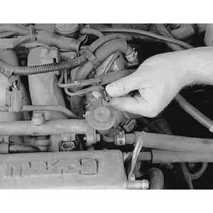
    Fig. 5: Remove the vacuum line from the fuel pressure regulator . . .

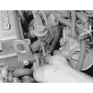
    Fig. 6: . . . then disconnect the fuel lines. Also, remove the fuel line retaining clamp bolt from the side of the intake manifold

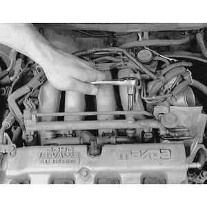
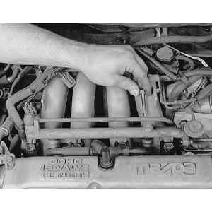
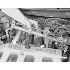
    Fig. 7: Loosen the fuel distributor attaching bolts evenly . . .

    Fig. 8: . . . then remove them

    Fig. 9: Lift the complete fuel distributor/injector assembly from the engine. The spacers (arrows) may remain on the intake . . .

    Fig. 10: . . . or stick to the fuel distributor. Ensure that you have both of them and do not lose them

  4. Detach the electrical connectors from the injectors and remove the wiring harness.
  5. Disconnect the vacuum hose from the pressure regulator.
  6. Disconnect the fuel lines from the fuel distributor and remove the fuel line attaching bolt on the side of the intake manifold.

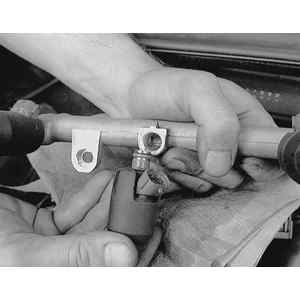
    Fig. 11: Remove the old insulators from the injectors and discard them

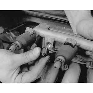
    Fig. 12: Remove the injector from the fuel distributor by pulling outward while slightly twisting the injector

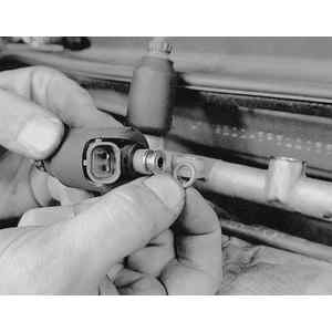
    Fig. 13: Also remove the old injector-to-fuel distributor O-ring seal and discard them. Always install new insulators and O-rings when installing

  7. Remove the bolts from the fuel distributor and remove the it with injectors attached.
  8. Remove the injectors complete with the O-rings and the insulators from the fuel distributor.

    To install:

  9. Replace the fuel injector O-rings and apply a small amount of clean engine oil to the O-rings before installation.
  10. Replace the injector insulators and install the injectors to the fuel distributor. Make sure that the injectors are properly seated and that the electrical connector points are facing upward.
  11. Install the fuel distributor to the intake manifold, making sure that the injectors are properly seated. Tighten the top bolts to 14–18 ft. lbs. (19–25 Nm) and the side bolt to 70–95 inch lbs. (8–11 Nm).
  12. Connect the fuel lines to the fuel distributor and to the pressure regulator.
  13. Connect the electrical harness to the injectors.
  14. If removed, install the air intake piping around the throttle body.
  15. Connect the negative battery cable.
2.2L ENGINE
  1. Properly relieve the fuel system pressure.
  2. Disconnect the negative battery cable.
  3. Remove the wiring harness bracket from the end of the engine.
  4. Remove the EGR modulator valve and remove the bracket.
  5. Disconnect the vacuum pipe mounting bolts.
  6. Remove the intake air hose from the throttle body.
  7. Remove the side engine lift hook assembly.
  8. Remove the dynamic chamber mounting bolts and nuts and lift the dynamic chamber away from the engine.
  9. Disconnect the fuel return pipe bracket from the intake manifold.
  10. Detach the fuel injector electrical connectors.
  11. Remove the fuel delivery pipe with the pressure regulator and pulsation damper intact.
  12. Separate the fuel injectors from the delivery pipe. Remove the grommets and the insulators.

    To install:

  13. Position the insulators and fuel injectors into the intake manifold. Position the grommets and new O-rings onto the fuel injectors. Apply a small amount of engine oil to the O-rings during installation.
  14. Position the spacers and the fuel distributor on the injectors. Install the attaching bolts to the fuel distributor and tighten to 14–19 ft. lbs. (19–25 Nm).
  15. Attach the electrical connectors to the fuel injectors.
  16. Install the fuel return line bracket onto the intake manifold and install the return fuel line at the bracket. Secure with the clamp.
  17. Connect the fuel return pipe bracket to the intake manifold.
  18. Lower the dynamic chamber into place and tighten the mounting bolts to 14–19 ft. lbs. (19–25 Nm).
  19. Install the side engine lift hook assembly and tighten the bolts to 14–19 ft. lbs. (19–25 Nm).
  20. Install the intake air hose to the throttle body.
  21. Install the vacuum pipe mounting bolts.
  22. Install the EGR modulator valve and bracket.
  23. Install the wiring harness bracket at the end of the intake manifold.
  24. Connect the negative battery cable.
MX-3, 626/MX-6/Probe and Millenia with V6 Engines

Fig. 14: When installing the injector on V6 engines, replace the O-rings and lightly oil them with engine oil

Fig. 15: Align the tab on the injector with the notches on the fuel distributor and wire harness connector

1.8L (K8) AND 2.5L ENGINES
  1. Relieve the fuel system pressure.
  2. Disconnect the negative battery cable.
  3. Remove the air intake hose assembly.
  4. Detach the injector electrical connectors from the injector harness.
  5. Disconnect the fuel hoses from the end of the fuel distributor.
  6. Remove the fuel distributor attaching screws and remove the fuel distributor.
  7. Remove the fuel injector harnesses from the fuel distributor.
  8. Separate the injectors from the distributor and remove the O-ring and spacer.

    To install:

  9. Replace the fuel injector O-rings and apply a small amount of clean engine oil to the O-rings before installation.
  10. Install the injectors to the fuel distributor. Turn until the injector is fully seated, aligning the tab on the injector with the notch in the fuel distributor.
  11. Install the injector harness on the fuel distributor and install the assembly to the engine.
  12. Tighten the fuel distributor screws to 22–31 inch lbs. (2.5–3.5 Nm).
  13. Connect the fuel hoses to the fuel distributor and attach the electrical connectors to the injector harness.
  14. Install the air intake hose and connect the negative battery cable.
2.3L ENGINE
  1. Relieve the fuel system pressure, and disconnect the negative battery cable.
  2. Remove the charge air cooler air duct.
  3. Remove the air cleaner assembly.
  4. Remove the resonator.
  5. Remove the left and right-hand charge air coolers.

    Fig. 16: Exploded view of the fuel injectors and related components for the 2.3L engine

  6. Disconnect the accelerator cable.
  7. Remove the air intake pipe assembly.
  8. Remove the vacuum hose assembly.
  9. Label and detach the fuel injector electrical connectors.
  10. Disconnect and plug the fuel supply and return lines. Discard the copper crush washers.
  11. Remove the fuel distributor mounting bolts and the fuel distributors.
  12. Remove the six insulators.
  13. Remove the distribution harness (accumulated connector) attaching screws, and remove the distribution harness from the fuel distributors.
  14. Remove and discard the spacer from the top of each fuel injector. Remove the fuel injectors from the fuel distributors by rotating back and forth.
  15. Remove the fuel pressure regulator mounting bolts and the fuel pressure regulator.

    To install:

  16. Install the fuel pressure regulator and tighten the bolts to 61–86 inch lbs. (7–10 Nm).
  17. Apply clean engine oil to new O-rings and install them on the injectors. Install the injectors into the fuel distributors.
  18. Install new spacers on the injectors, then install the distribution harness with the screws. Tighten the screws to 22–31 inch lbs. (2.5–3.5 Nm).
  19. Install the 6 insulators and the fuel distributors. Install the fuel distributor mounting bolts and tighten to 14–18 ft. lbs. (19–25 Nm).
  20. Using new copper crush washers, connect the fuel supply and return lines.
  21. Attach the fuel injector electrical connectors.
  22. Install the vacuum hose assembly. Tighten the mounting nuts to 70–95 inch lbs. (8–11 Nm).
  23. Install the air intake pipe assembly. Tighten the mounting nuts to 70–95 inch lbs. (8–11 Nm), and the mounting bolts to 44–78 inch lbs. (5–9 Nm).
  24. Connect and adjust the accelerator cable. Tighten the mounting bolt to 70–95 inch lbs. (8–11 Nm).
  25. Install the left and right-hand charge air coolers. Install new O-rings, and tighten the bolts to 14–18 ft. lbs. (19–25 Nm).
  26. Install the resonator. Tighten the mounting nuts to 70–95 inch lbs. (8–11 Nm).
  27. Install the air cleaner assembly. Tighten the mounting nuts to 70–95 inch lbs. (8–11 Nm).
  28. Install the charge air cooler air duct. Tighten the mounting nuts to 70–95 inch lbs. (8–11 Nm).
  29. Connect the negative battery cable. Turn the ignition switch ON to pressurize the fuel system. Check for fuel leaks and correct as necessary before starting the engine.

Previous Next