Previous Next

Fuel Pressure Regulator

REMOVAL & INSTALLATION

Fig. 1: Exploded view of a typical 4-cylinder engine fuel pressure regulator

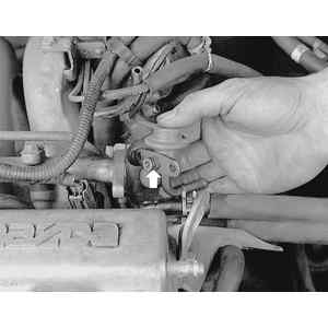
Fig. 2: Typical 6-cylinder engine fuel pressure regulator location

MX-3 with 4-Cylinder Engine, 323 and Protege
  1. Properly relieve the fuel system pressure.
  2. Disconnect the vacuum hose from the pressure regulator.
  3. Disconnect the fuel return hose from the pressure regulator.
  4. Remove the pressure regulator attaching bolts and remove the fuel pressure regulator assembly.
  5. Installation is the reverse of the removal procedure. Replace the O-ring and tighten the attaching bolts to 69–95 inch lbs. (8–11 Nm).
626/MX-6/Probe with 4-Cylinder Engines
2.0L ENGINE
  1. Properly relieve the fuel system pressure.
  2. Disconnect the vacuum hose from the pressure regulator.

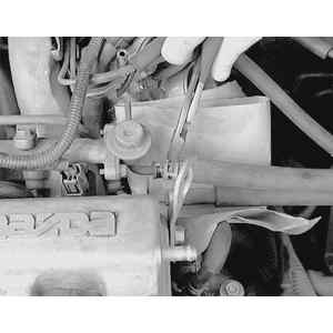
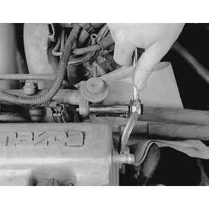
    Fig. 3: To remove the fuel pressure regulator, first relieve the system pressure, then slide the fuel hose clamp backwards . . .

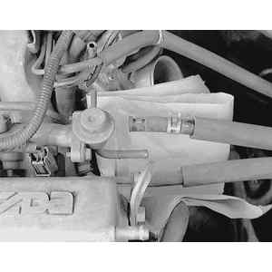
    Fig. 4: . . . and disconnect the fuel hose from the regulator. A rag positioned beneath the hose will catch any spilled fuel

    Fig. 5: Remove the fuel pressure regulator attaching bolts . . .

    Fig. 6: . . . then pull the regulator from the fuel distributor. Always replace the O-ring seal (arrow) on the regulator when installing

  3. Disconnect the fuel return hose from the pressure regulator.
  4. Remove the pressure regulator attaching bolts and remove the fuel pressure regulator assembly.
  5. Installation is the reverse of the removal procedure. Replace the O-ring and tighten the attaching bolts to 70–95 inch lbs. (7.8–10.7 Nm.)
2.2L ENGINE
  1. Properly relieve the fuel system pressure.
  2. Disconnect the negative battery cable.
  3. Remove the wiring harness bracket from the end of the engine.
  4. Remove the EGR modulator valve and remove the bracket.
  5. Disconnect the vacuum pipe mounting bolts.
  6. Remove the intake air hose from the throttle body.
  7. Remove the side engine lift hook assembly.
  8. Remove the dynamic chamber mounting bolts and nuts and lift the dynamic chamber away from the engine.
  9. Disconnect the fuel return pipe bracket from the intake manifold.
  10. Disconnect the vacuum hose and the fuel return hose.
  11. Remove the pressure regulator attaching bolts and remove the fuel pressure regulator.

    To install:

  12. Install the fuel pressure regulator and tighten the attaching bolts to 69–95 inch lbs. (7.8–11 Nm).
  13. Connect the vacuum hose and the fuel return hose to the fuel pressure regulator.
  14. Install the fuel return line bracket onto the intake manifold and install the return fuel line at the bracket. Secure with the clamp.
  15. Connect the fuel return pipe bracket to the intake manifold.
  16. Lower the dynamic chamber into place and tighten the mounting bolts to 14–19 ft. lbs. (19–25 Nm).
  17. Install the side engine lift hook assembly and tighten the bolts to 14–19 ft. lbs. (19–25 Nm).
  18. Install the intake air hose to the throttle body.
  19. Install the vacuum pipe mounting bolts.
  20. Install the EGR modulator valve and bracket.
  21. Install the wiring harness bracket at the end of the intake manifold.
  22. Connect the negative battery cable.
MX-3, 626/MX-6/Probe and Millenia with V6 Engines
  1. Relieve the fuel system pressure.
  2. Disconnect the negative battery cable.
  3. Remove the air cleaner assembly.
  4. If necessary, detach the injector electrical connectors from the injector harness.
  5. Disconnect the fuel hoses from the fuel distributor.
  6. Remove the fuel distributor attaching screws and remove the fuel distributor.
  7. Remove the injector harnesses from the fuel distributor.
  8. Disconnect the vacuum hose and the fuel return hose from the pressure regulator.
  9. Remove the attaching bolts and remove the pressure regulator from the fuel distributor.

    To install:

  10. Install the fuel pressure regulator to the fuel distributor and tighten the bolts to 61–87 inch lbs. (7–10 Nm).
  11. Connect the vacuum hose and the fuel return line to the fuel pressure regulator.
  12. Align the fuel injector tabs with the distributor and install the distributor assemblies.
  13. Tighten the fuel distributor screws to 22–31 inch lbs. (2.5–3.5 Nm).
  14. Connect the fuel hose to the fuel distributor and, if removed, attach the electrical connectors to the injector harness.
  15. Install the air cleaner assembly and connect the negative battery cable.

Previous Next