Previous Next

Control Panel

REMOVAL & INSTALLATION

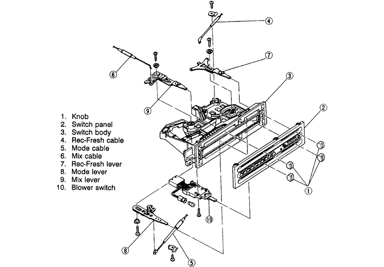
Fig. 1: Exploded view of a typical cable type heater control unit

MX-3, 1990–94 323 and Protege
  1. Disconnect the negative battery cable.
  2. From the right side of the dash, remove the side trim panel.
  3. From directly below the glovebox, remove the trim panel.
  4. Remove the center trim panel.
  5. Remove the upper and lower instrument cluster assemblies. Disconnect the electrical connectors from the top assembly.
  6. Remove the glove box and the inside glove box lining.
  7. Remove the control panel retaining screws and disconnect the control cable wires from the control panel. Remove the control panel from the vehicle.

    To install:

  8. Connect the control cable wires to the control panel and install the panel assembly.
  9. Install the glove box and the inside glove box lining.
  10. Install the instrument cluster upper and lower assemblies. Make sure to connect all of the electrical connectors.
  11. Install the center trim panel assembly.
  12. Install the trim panel below the glovebox and install the side trim panel.
  13. Connect the negative battery cable.
1990–92 626/MX-6
  1. Disconnect the negative battery cable.
  2. Remove the bezel cover from the control assembly face.
  3. Remove the 4 attaching screws from the control assembly housing.
  4. Remove the passenger and driver side sound deadening panels.
  5. Remove the REC/FRESH control cable at the REC/FRESH selector door assembly.
  6. Disconnect the blower switch electrical connector and the control assembly illumination electrical connector.
  7. Remove the temperature control cable from the temperature blend door assembly at the right-hand side of the heater case.
  8. Remove the function selector cable from the function control door assembly at the left-hand side of the heater case.
  9. Remove the control assembly and control cables as an assembly.

    NOTE: While removing the control panel assembly, notice how the cables are routed for proper installation

    To install:

  10. Position the control panel assembly into the instrument panel while routing the control cables as noted during removal.
  11. Connect the blower switch and control assembly illumination electrical connectors.
  12. Secure the control assembly with the 4 attaching screws.
  13. Install the plastic bezel cover onto the face of the control assembly.
  14. Install and adjust all control cables to their respective control and selector door assemblies and adjust the cables. Refer to the procedures in this Section.
  15. Install both sound deadening panels.
  16. Connect the negative battery cable. Check for proper control assembly operation.
1993–98 626/MX-6/Probe
  1. Disconnect the negative battery cable.
  2. Remove the upper and lower steering wheel panels.
  3. Remove the lower dash panel. Make sure to disconnect the switch connectors.
  4. Remove the heater control unit mounting screws and pull the unit out.
  5. Disconnect the electrical connectors from the control unit and remove the control unit.
  6. Installation is the reverse of the removal procedure. Make sure to connect all of the electrical connectors and test all accessories when done.
Millenia
  1. Disconnect the negative battery cable.
  2. Remove the upper and lower steering wheel panels.
  3. Remove the hazard warning switch as follows:
    1. Remove the instrument cluster trim panel.
    2. Detach the hazard warning switch electrical connector.
    3. Remove the switch-to-trim panel retaining screw and remove the switch from the panel.

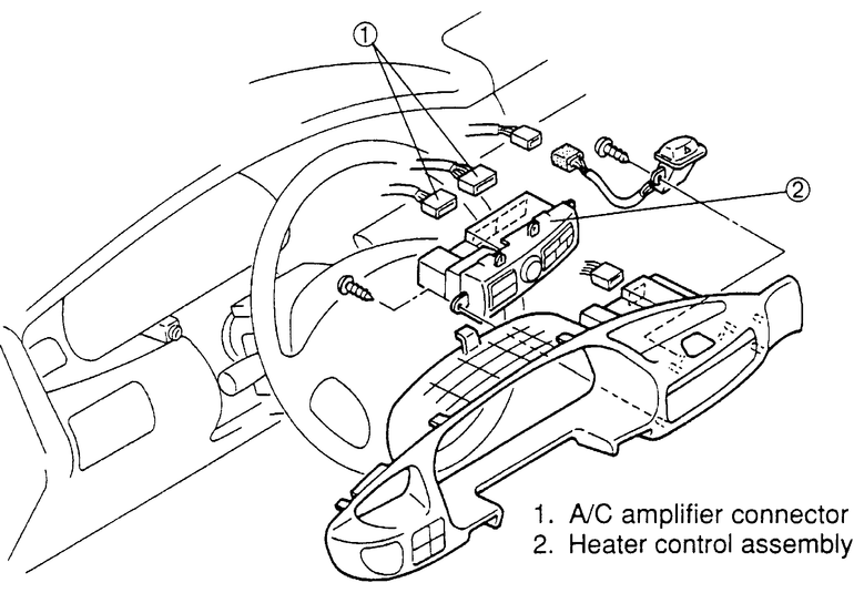
      Fig. 2: Exploded view of the Millenia heater control unit

  4. Detach the electrical wire connectors from the back of the heater control unit.
  5. Remove the heater control-to-trim panel retaining screws and remove the control unit from the panel.
  6. Installation is the reverse of the removal procedure. Use care when tightening the control unit and hazard switch retaining screws so as not to damage the plastic trim panel.

Previous Next