| Fig. 1: Exploded view of the halfshaft assemblies
and related components
|
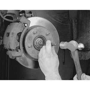
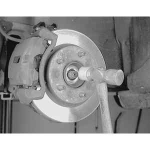
| Fig. 2: To remove the halfshaft, first raise and
support the vehicle. Remove the wheel, then raise the staked portion
of the hub locknut
|
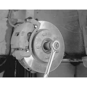
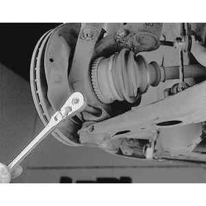
| Fig. 3: Have an assistant apply the brakes and loosen
the hub locknut . . .
|
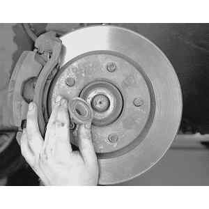
| Fig. 4: . . . then remove and discard it. Always
install a new hub locking nut when installing the halfshaft
|
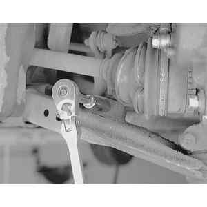
| Fig. 5: Loosen the stabilizer bar end link-to-control
arm retaining nut . . .
|
| Fig. 6: . . . and disengage the link from the control
arm bracket
|
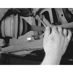
| Fig. 7: Remove the lower ball joint pinch bolt and
nut . . .
|
| Fig. 8: . . . and disengage the ball joint from the
steering knuckle. Some careful prying may be necessary, but use care
near the dust boot
|
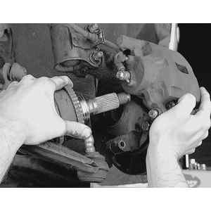
| Fig. 9: Pull outward on the knuckle assembly and
withdraw the splined axleshaft from the wheel hub
|
| Fig. 10: If the axleshaft end seems stuck in the
wheel hub, gently tap it with a soft faced hammer to break it loose
|
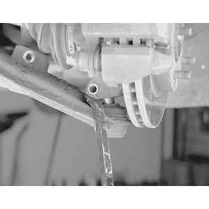
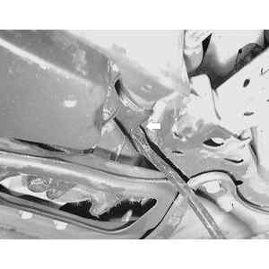
| Fig. 11: With the outer end of the halfshaft free,
use a prybar and remove the inner end from the transaxle case . .
.
|
| Fig. 12: . . . then remove the entire axleshaft from
the vehicle
|
NOTE: Install plug tool 49 G030 455 or equivalent, into the transaxle after removing the halfshaft, to keep the differential side gear in position. If the gear becomes mispositioned, the differential may have to be removed to realign the gear.
To install: