Previous Next

Lower Control Arms

REMOVAL & INSTALLATION

Millenia
  1. Raise and safely support the vehicle.
  2. Remove the transverse member.
  3. Disconnect the power steering return hose and pressure pipe.
  4. Remove the intermediate steering shaft bolt.
  5. Support the engine from the top and remove the engine mount member.

    Fig. 1: Exploded view of the Millenia front suspension assembly

  6. Remove the bolts for engine mount No. 1.
  7. Remove the lower strut mounting bolt.
  8. Disconnect the tie-rod end from the steering knuckle.
  9. Remove the upper lateral link ball joint.
  10. Remove the lower ball joint.
  11. Remove the stabilizer control link nut.
  12. Remove the gusset.
  13. Support the crossmember using a jack and remove the crossmember mounting nuts. Lower the crossmember to gain clearance and remove the lower arm assembly.

    To install:

  14. Replace the lower arm assembly to the vehicle and install the crossmember mounting bolts.
  15. Install the gusset, torque the gusset mount bolts to 58–86 ft. lbs. (79–116 Nm).
  16. Connect the stabilizer control link, torque the nut to 32–44 ft. lbs. (44–60 Nm).
  17. Install the lower ball joint, torque the mounting bolts to 58–86 ft. lbs. (79–116 Nm). Torque the retaining nut at the knuckle to 86–115 ft. lbs. (116–156 Nm).
  18. Install the upper lateral link nut and bolt, torque to 58–86 ft. lbs. (79–116 Nm).
  19. Connect the tie-rod end, torque the nut to 41–59 ft. lbs. (55–80 Nm).
  20. Install the strut lower mounting bolt and torque to 73–101 ft. lbs. (98–137 Nm).
  21. Install the No. 1 engine mount bolts and torque to 32–44 ft. lbs. (44–60 Nm).
  22. Install the engine mount member, torque the bolts to 50–68 ft. lbs. (67–93 Nm) and the nuts to 55–77.3 ft. lbs. (75–104 Nm). Remove the engine support tool.
  23. Install the intermediate steering shaft bolt, torque to 14–19 ft. lbs. (18–26 Nm).
  24. Connect the power steering pressure pipe and return hose.
  25. Install the transverse member.
  26. Lower the vehicle. Check the power steering fluid and fill to proper level, bleed if necessary. Check the front end alignment.
Except Millenia
  1. Raise and safely support the vehicle. Remove the wheel and tire assembly.

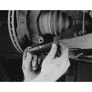
    Fig. 2: To remove the control arm, first, raise and support the vehicle then remove the wheel. Loosen the stabilizer bar end link nut . . .

    Fig. 3: . . . and detach the end link from the control arm

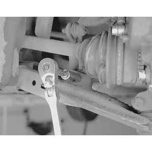
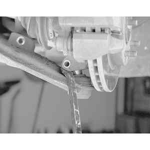
    Fig. 4: Loosen the lower ball joint pinch bolt . . .

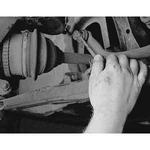
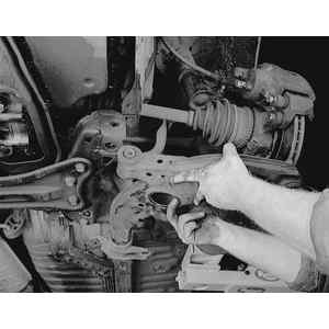
    Fig. 5: . . . remove the bolt and nut from the steering knuckle . . .

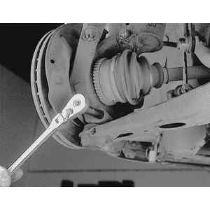
    Fig. 6: . . . and disengage the lower ball joint from the steering knuckle

  2. Disconnect the stabilizer bar link from the lower control arm.

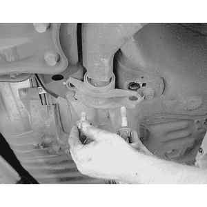
    Fig. 7: Loosen the rear control arm bushing bracket retaining bolts . . .

    Fig. 8: . . . and remove them. Note that the bolts are of different length so mark them to ensure proper installation

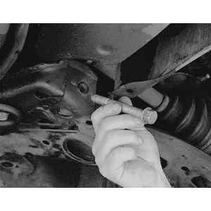
    Fig. 9: Loosen the front control arm through-bolt . . .

    Fig. 10: . . . then withdraw the bolt. Some gentle tapping with a hammer and drift pin may be necessary

  3. Remove the lower ball joint pinch bolt from the steering knuckle.
  4. Seperate the lower ball joint from the steering knuckle.

    Fig. 11: Remove the control arm from the vehicle

  5. Remove the lower control arm bolts and nuts and remove the lower control arm.

    To install:

  6. Install the lower control arm and loosely tighten the mounting nuts and bolts.
  7. Connect the lower ball joint to the steering knuckle. Install the pinch bolt and tighten to specifications.
  8. Connect the stabilizer link to the lower control arm.
  9. Install the wheel and tire assembly and lower the vehicle. With the vehicle at normal ride height, tighten the lower control arm mounting bolts.
  10. Check the front wheel alignment.

Previous Next