Previous Next

Rear Control Arms and Links

REMOVAL & INSTALLATION

323/Protege, MX-3 and 1990–92 MX6, 626
  1. Raise and safely support the vehicle and remove the wheels.
  2. Before disconnecting the stabilizer bar link, on all except MX-3, measure the length of the threads protruding above the locknut. Remove the nuts and through bolt to disconnect the stabilizer bar.
  3. Remove the nuts and bolts as required and remove the control arms.
  4. Installation is the reverse of removal. Make sure to properly adjust the stabilizer bar before tightening the locknuts and check rear wheel alignment.
Millenia and 1993–98 626/MX-6/Probe
  1. Raise and safely support the vehicle. Remove the wheel and tire assemblies.

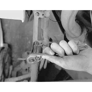
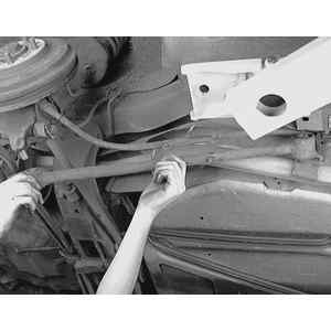
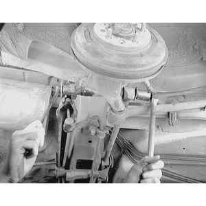
    Fig. 1: To remove the trailing arm, first unbolt any brackets (such as for brake cables) which are attached to the arm . . .

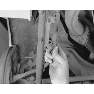
    Fig. 2: . . . and position them out of the way

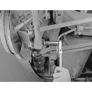
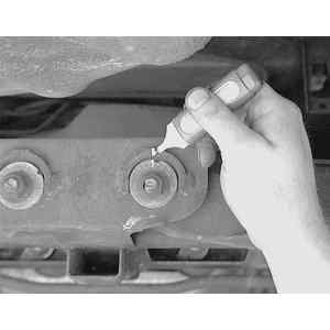
    Fig. 3: Remove the trailing arm-to-wheel mount attaching bolt and disengage the arm

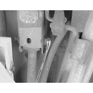
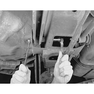
    Fig. 4: Remove the trailing arm-to-chassis through-bolt . . .

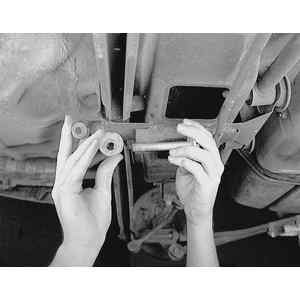
    Fig. 5: . . . and pull the trailing arm backwards and remove it from the vehicle

  2. Remove the access cap from the underside of the rear crossmember.
  3. Remove the bolts and nuts and remove the lateral links and trailing link. If removing the rear lateral link, paint an alignment mark on the cam plate and crossmember for assembly reference.

    Fig. 6: To remove a lateral link, first matchmark any alignment cams to ensure proper installation . . .

    Fig. 7: . . . then loosen the link-to-center chassis attaching bolt . . .

    Fig. 8: . . . and remove the bolt, nut and alignment cam

    Fig. 9: Remove the lateral link-to-wheel mount through-bolt, then detach the link and remove it from the vehicle

  4. Installation is the reverse of the removal procedure.
  5. Do not final tighten the bolts until the vehicle is on the ground and at normal ride height.

Previous Next