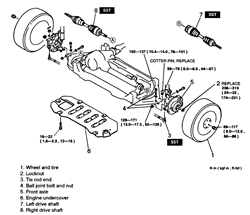
| Fig. 1: Exploded view of the halfshaft and related components — 1997–98
4WD vehicles

|
- Before servicing the vehicle, refer to the precautions in the beginning
of this section.
- Remove or disconnect the following:
- Front wheel
- Hub retainer nut
- Outer tie rod end
- Lower ball joint
- Engine under cover
- Separate the inner joint from the differential housing with a prybar.
- Separate the stub shaft from the hub and remove the axle halfshaft from
the vehicle.
To install:
NOTE: Use new circlips, split pins and locknuts for assembly.
- Install the inner joint to the differential so that the circlip is seated.
- Guide the stub shaft into the hub.
- Install or connect the following:
- Engine under cover
- Lower ball joint. Tighten the horizontal bolt to 95–126 ft. lbs.
(128–171 Nm) and the vertical bolts to 76–101 ft. lbs. (102–137
Nm).
- Outer tie rod end. Tighten the nut to 44–57 ft. lbs. (59–78
Nm).
- Hub retainer nut. Tighten the locknut to 174–231 ft. lbs. (236–313
Nm).
- Front wheel
- Before servicing the vehicle, refer to the precautions in the beginning
of this section.
- Drain the transaxle fluid.
- Remove or disconnect the following:
- Front wheel
- Wheel speed sensor
- Hub locknut
- Outer tie rod end
- Lower ball joint
- Stabilizer bar link
- Separate the stub shaft from the hub and pry the inner joint from the transaxle.
To install:
NOTE: Use a new circlip, split pin and locknut for assembly.
- Insert the stub shaft into the wheel hub.
- Lubricate the oil seal with transaxle fluid, then push the axle halfshaft
into the transaxle. Pull on the inner joint to confirm that the circlip is
seated.
- Install or connect the following:
- Stabilizer bar link
- Lower ball joint. Tighten the pinch bolt to 32–43 ft. lbs. (44–58
Nm).
- Outer tie rod end. Tighten the nut to 24–32 ft. lbs. (32–44
Nm).
- Hub locknut. Tighten the nut to 174–235 ft. lbs. (236–318
Nm).
- Wheel speed sensor
- Front wheel
WARNING
Attempting to remove the right axle halfshaft while the center shaft support
bracket is installed may result in damage to the center shaft support bracket.
- Before servicing the vehicle, refer to the precautions in the beginning
of this section.
- Remove or disconnect the following:
- Front wheel
- Wheel speed sensor
- Hub locknut
- Brake caliper and rotor
- Outer tie rod end
- Lower ball joint
- Strut bracket bolts
- Steering knuckle. Separate the stub shaft from the wheel hub.
- Center shaft support bracket
- Axle halfshaft and center shaft assembly
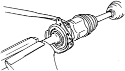
- Separate the axle halfshaft and the center shaft as follows:
- Step 1: Place the center shaft in a vise
- Step 2: Insert a pry tool between the center shaft and the axle halfshaft
- Step 3: Tap on the pry tool to separate the axle halfshaft from the
center shaft
| Fig. 2: Separating the axle halfshaft from the
center shaft — 2000–01 MPV

|
To install:
NOTE: Use a new split pin, locknut, and new circlips
for assembly.
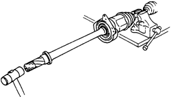
- Place the axle halfshaft in a vise and install the center shaft by tapping
it with a plastic hammer as shown.
| Fig. 3: Installing the center shaft — 2000–01
MPV

|
- Lubricate the oil seal with transaxle fluid, then push the center shaft
into the transaxle. Pull on the inner joint to confirm that the circlip is
seated.
- Install or connect the following:
- Center shaft support bracket. Tighten the nuts to 16–22 ft. lbs.
(22–30 Nm).
- Steering knuckle. Guide the stub shaft into the wheel hub.
- Strut bracket bolts. Tighten the bolts to 76–90 ft. lbs. (103–122
Nm).
- Lower ball joint. Tighten the pinch bolt to 32–43 ft. lbs. (44–58
Nm).
- Outer tie rod end. Tighten the nut to 24–32 ft. lbs. (32–44
Nm).
- Hub locknut. Tighten the nut to 174–235 ft. lbs. (236–318
Nm).
- Brake caliper and rotor. Tighten the caliper bracket bolts to 66–79
ft. lbs. (89–107 Nm).
- Wheel speed sensor
- Front wheel
- Check the wheel alignment and adjust as necessary.


