The best, and most accurate method to test the operation of an Oxygen
(O2S) sensor is with the use of either an oscilloscope or a Diagnostic
Scan Tool (DST), following their specific instructions for testing. It
is possible, however, to test whether the O2S sensor is functioning properly
within general parameters using a Digital Volt-Ohmmeter (DVOM), also referred
to as a Digital Multi-Meter (DMM). Newer DMM's are often designed to perform
many advanced diagnostic functions. Some are constructed to be used as
an oscilloscope. Two in-vehicle testing procedures, and 1 bench test procedure,
will be provided for the common zirconium dioxide O2S sensor. The first
in-vehicle test makes use of a standard DVOM with a 10 megohms impedance,
whereas the second in-vehicle test presented necessitates the usage of
an advanced DMM with MIN/MAX/Average functions. Both of these in-vehicle
test procedures are likely to set Diagnostic Trouble Codes (DTC's) in
the engine control computer. Therefore, after testing, be sure to clear
all DTC's before retesting the sensor, if necessary.
These are some of the common DTC's which may be set during testing:
- Open in the O2S sensor circuit
- Constant low voltage in the O2S sensor circuit
- Constant high voltage in the O2S sensor circuit
- Other fuel system problems could set a O2S sensor
code
NOTE: Because an improperly functioning fuel delivery
and/or control system can adversely affect the O2S sensor voltage output
signal, testing only the O2S sensor is an inaccurate method for diagnosing
an engine driveability problem.
If after testing the sensor, the sensor is thought to be defective because
of high or low readings, be sure to check that the fuel delivery and engine
management system is working properly before condemning the O2S sensor.
Otherwise, the new O2S sensor may continue to register the same high or
low readings.
Often, by testing the O2S sensor, another problem in the engine control
management system can be diagnosed. If the sensor appears to be defective
while installed in the vehicle, perform the bench test. If the sensor
functions properly during the bench test, chances are that there may be
a larger problem in the vehicle's fuel delivery and/or control system.
Many things can cause an O2S sensor to fail, including old age, antifreeze
contamination, physical damage, prolonged exposure to overly-rich exhaust
gases, and exposure to silicone sealant fumes. Be sure to remedy any such
condition prior to installing a new sensor, otherwise the new sensor may
be damaged as well.
NOTE: Perform a visual inspection of the sensor. Black
sooty deposits may indicate a rich air/fuel mixture, brown deposits may
indicate an oil consumption problem, and white gritty deposits may indicate
an internal coolant leak. All of these conditions can destroy a new sensor
if not corrected before installation.
The easiest method for determining sensor terminal identification is
to use a wiring diagram for the vehicle and engine in question. However,
if a wiring diagram is not available there is a method for determining
terminal identification. Throughout the testing procedures, the following
terms will be used for clarity:
- Vehicle harness connector — this refers to the
connector on the wires which are attached to the vehicle, NOT the connector
at the end of the sensor pigtail
- Sensor pigtail connector — this refers to the
connector attached to the sensor itself
- Oxygen (O2S) sensor circuit — this refers to
the circuit in a Heated Oxygen (HO2S) sensor which corresponds to the
oxygen-sensing function of the sensor; NOT the heating element circuit
- Heating circuit — this refers to the circuit
in a HO2S sensor which is designed to warm the HO2S sensor quickly to
improve driveability
- Sensor Output ( SOUT) terminal — this
is the terminal which corresponds to the O2S circuit output. This is the
terminal that will register the millivolt signals created by the sensor
based upon the amount of oxygen in the exhaust gas stream.
- Sensor Ground ( SGND) terminal — when
a sensor is so equipped, this refers to the O2S circuit ground terminal.
Many O2S sensors are not equipped with a ground wire, rather they utilize
the exhaust system for the ground circuit.
- Heating Power ( HPWR) terminal — this
terminal corresponds to the circuit which provides the O2S sensor heating
circuit with power when the ignition key is turned to the ON or
RUN positions
-
Heating Ground ( HGND) terminal — this is the terminal
connected to the heating circuit ground wire
| Fig. 1: Wiring schematic of typical 1-, 2-, 3- and
4-wire oxygen sensor circuits

|
1-wire sensors are by far the easiest to determine sensor terminal identification,
but this is self-evident. On 1-wire O2S sensors, the single wire terminal
is the SOUT and the exhaust system is used to provide the sensor
ground pathway. Proceed to the test procedures.
On 2-wire sensors, one of the connector terminals is the SOUT
and the other is the SGND. To determine which one is which, perform
the following:
- Locate the Oxygen (O2S) sensor and its pigtail connector.
It may be necessary to raise and safely support the vehicle to gain access
to the connector.
- Start the engine and allow it to warm up to normal
operating temperature, then turn the engine OFF.
-
Using a Digital Volt Ohm Meter (DVOM) set to read 100–900 mV (millivolts)
DC, backprobe the positive DVOM lead to one of the unidentified terminals
and attach the negative lead to a good engine ground.
CAUTION
While the engine is running, keep clear of all moving and hot components.
Do not wear loose clothing. Otherwise severe personal injury or death
may occur.
- Have an assistant restart the engine and allow it
to idle.
- Check the DVOM for voltage.
- If no voltage is evident, check your DVOM leads to
ensure that they are properly connected to the terminal and engine ground.
If still no voltage is evident at the first terminal, move the positive
meter lead to backprobe the second terminal.
- If voltage is now present, the positive meter lead
is attached to the SOUT terminal. The remaining terminal is the
SGND terminal. If still no voltage is evident, either the O2S sensor
is defective or the meter leads are not making adequate contact with the
engine ground and terminal contacts; clean the contacts and retest. If
still no voltage is evident, the sensor is defective.
- Have your assistant turn the engine OFF.
- Label the sensor pigtail SOUT and SGND
terminals.
- Proceed to the test procedures.
NOTE: 3-wire sensors are HO2S sensors.
On 3-wire sensors, one of the connector terminals is the SOUT,
one of the terminals is the HPWR and the other is the HGND.
The SGND is achieved through the exhaust system, as with the 1-wire
O2S sensor. To identify the 3 terminals, perform the following:
- Locate the O2S sensor and its pigtail connector.
It may be necessary to raise and safely support the vehicle to gain access
to the connector.
- Disengage the sensor pigtail connector from the vehicle
harness connector.
- Using a Digital Volt Ohm Meter (DVOM) set to read
12 volts, attach the DVOM ground lead to a good engine ground.
- Have an assistant turn the ignition switch ON
without actually starting the engine.
-
Probe all 3 terminals in the vehicle harness connector. One of the
terminals should exhibit 12 volts of power with the ignition key ON;
this is the HPWR terminal.
- If the HPWR terminal was identified, note
which of the sensor harness connector terminals is the HPWR, then
match the vehicle harness connector to the sensor pigtail connector. Label
the corresponding sensor pigtail connector terminal with HPWR.
- If none of the terminals showed 12 volts of power,
locate and test the heater relay or fuse. Then, perform Steps 3–6 again.
- Start the engine and allow it to warm up to normal
operating temperature, then turn the engine OFF.
- Have your assistant turn the ignition OFF.
-
Using the DVOM set to measure resistance (ohms), attach one of the
leads to the HPWR terminal of the sensor pigtail connector. Use
the other lead to probe the 2 remaining terminals of the sensor pigtail
connector, one at a time. The DVOM should show continuity with only one
of the remaining unidentified terminals; this is the HGND terminal.
The remaining terminal is the SOUT.
- If continuity was found with only one of the
2 unidentified terminals, label the HGND and SOUT terminals
on the sensor pigtail connector.
- If no continuity was evident, or if continuity
was evident from both unidentified terminals, the O2S sensor is defective.
- All 3-wire terminals should now be labeled on the
sensor pigtail connector. Proceed with the test procedures.
NOTE: 4-wire sensors are HO2S sensors.
On 4-wire sensors, one of the connector terminals is the SOUT,
one of the terminals is the SGND, one of the terminals is the
HPWR and the other is the HGND. To identify the 4 terminals,
perform the following:
- Locate the O2S sensor and its pigtail connector.
It may be necessary to raise and safely support the vehicle to gain access
to the connector.
- Disengage the sensor pigtail connector from the vehicle
harness connector.
- Using a Digital Volt Ohm Meter (DVOM) set to read
12 volts, attach the DVOM ground lead to a good engine ground.
- Have an assistant turn the ignition switch ON
without actually starting the engine.
-
Probe all 4 terminals in the vehicle harness connector. One of the
terminals should exhibit 12 volts of power with the ignition key ON;
this is the HPWR terminal.
- If the HPWR terminal was identified, note
which of the sensor harness connector terminals is the HPWR, then
match the vehicle harness connector to the sensor pigtail connector. Label
the corresponding sensor pigtail connector terminal with HPWR.
- If none of the terminals showed 12 volts of power,
locate and test the heater relay or fuse. Then, perform Steps 2–6 again.
- Have your assistant turn the ignition OFF.
-
Using the DVOM set to measure resistance (ohms), attach one of the
leads to the HPWR terminal of the sensor pigtail connector. Use
the other lead to probe the 3 remaining terminals of the sensor pigtail
connector, one at a time. The DVOM should show continuity with only one
of the remaining unidentified terminals; this is the HGND terminal.
- If continuity was found with only 1 of the 2
unidentified terminals, label the HGND terminal on the sensor pigtail
connector.
- If no continuity was evident, or if continuity
was evident from all unidentified terminals, the O2S sensor is defective.
- If continuity was found at 2 of the other terminals,
the sensor is probably defective. However, the sensor may not necessarily
be defective, because it may have been designed with the 2 ground wires
joined inside the sensor in case one of the ground wires is damaged; the
other circuit could still function properly. Though, this is highly unlikely.
A wiring diagram is necessary in this particular case to know whether
the sensor was so designed.
- Reattach the sensor pigtail connector to the vehicle
harness connector.
- Start the engine and allow it to warm up to normal
operating temperature, then turn the engine OFF.
-
Using a DVOM set to read 100–900 mV (millivolts) DC, backprobe the
negative DVOM lead to one of the unidentified terminals and the positive
lead to the other unidentified terminal.
CAUTION
While the engine is running, keep clear of all moving and hot components.
Do not wear loose clothing. Otherwise severe personal injury or death
may occur.
- Have an assistant restart the engine and allow it
to idle.
-
Check the DVOM for voltage.
- If no voltage is evident, check your DVOM leads
to ensure that they are properly connected to the terminals. If still
no voltage is evident at either of the terminals, either the terminals
were accidentally marked incorrectly or the sensor is defective.
- If voltage is present, but the polarity is reversed
(the DVOM will show a negative voltage amount), turn the engine OFF
and swap the 2 DVOM leads on the terminals. Start the engine and ensure
that the voltage now shows the proper polarity.
- If voltage is evident and is the proper polarity,
the positive DVOM lead is attached to the SOUT and the negative
lead to the SGND terminals.
- Have your assistant turn the engine OFF.
- Label the sensor pigtail SOUT and SGND
terminals.
WARNING
Never apply voltage to the O2S circuit of the sensor, otherwise it may
be damaged. Also, never connect an ohmmeter (or a DVOM set on the ohm
function) to both of the O2S circuit terminals (
SOUT and
SGND) of the sensor pigtail connector;
it may damage the sensor.
Test 1 makes use of a standard DVOM with a 10 megohms impedance, whereas
Test 2 necessitates the usage of an advanced Digital Multi-Meter (DMM)
with MIN/MAX/Average functions or a sliding bar graph function. Both of
these in-vehicle test procedures are likely to set Diagnostic Trouble
Codes (DTC's) in the engine control computer. Therefore, after testing,
be sure to clear all DTC's before retesting the sensor, if necessary.
The third in-vehicle test is designed for the use of a scan tool or oscilloscope.
The 4th test (Heating Circuit Test) is designed to check the function
of the heating circuit in a HO2S sensor.
NOTE: If the O2S sensor being tested is designed to use
the exhaust system for the SGND, excessive corrosion between the
exhaust and the O2S sensor may affect sensor functioning.
The in-vehicle tests may be performed for O2S sensors located in the
exhaust system after the catalytic converter. However, the O2S sensors
located behind the catalytic converter will not fluctuate like the sensors
mounted before the converter, because the converter, when functioning
properly, emits a steady amount of oxygen. If the O2S sensor mounted after
the catalytic converter exhibits a fluctuating signal (like other O2S
sensors), the catalytic converter is most likely defective.
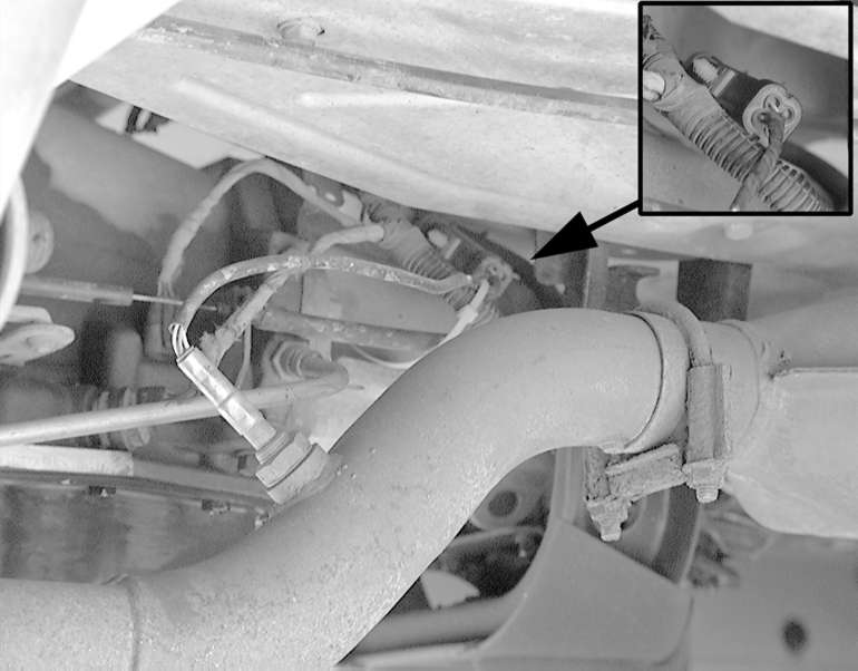
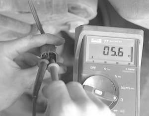
| Fig. 2: To test the O2S sensor, locate it and its connector
(inset), which should be positioned away from the exhaust system to prevent
heat damage.

|
This test will not only verify proper sensor functioning, but is also
designed to ensure the engine control computer and associated wiring is
functioning properly as well.
-
Start the engine and allow it to warm up to normal operating temperature.
NOTE: If you are using the opening of the thermostat
to gauge normal operating temperature, be forewarned: a defective thermostat
can open too early and prevent the engine from reaching normal operating
temperature. This can cause a slightly rich condition in the exhaust,
which can throw the O2S sensor readings off slightly.
- Turn the ignition switch OFF, then locate
the O2S sensor pigtail connector.
- Perform a visual inspection of the connector to ensure
it is properly engaged and all terminals are straight, tight and free
from corrosion or damage.
- Disengage the sensor pigtail connector from the vehicle
harness connector.
- On sensors equipped with a SGND terminal (sensors
which do not use the exhaust system for the sensor ground pathway), connect
a jumper wire to the SGND terminal and to a good, clean engine
ground (preferably the negative terminal of the battery).
-
Using a Digital Volt Ohm Meter (DVOM) set to read DC voltage, attach
the positive lead to the SOUT terminal of the sensor pigtail connector,
and the DVOM negative lead to a good engine ground.
CAUTION
While the engine is running, keep clear of all moving and hot components.
Do not wear loose clothing. Otherwise severe personal injury or death
may occur.
- Have an assistant start the engine and hold it at
approximately 2000 rpm. Wait at least 1 minute before commencing with
the test to allow the O2S sensor to sufficiently warm up.
- Using a jumper wire, connect the SOUT terminal
of the vehicle harness connector to a good engine ground. This
will fool the engine control computer into thinking it is receiving a
lean signal from the O2S sensor,, therefore, the computer will richen
the air/fuel ratio. With the SOUT terminal so grounded, the DVOM
should register at least 800 mV, as the control computer adds additional
fuel to the air/fuel ratio.
- While observing the DVOM, disconnect the vehicle
harness connector SOUT jumper wire from the engine ground. Use
the jumper wire to apply slightly less than 1 volt to the SOUT
terminal of the vehicle harness connector. One method to do this is by
grasping and squeezing the end of the jumper between your forefinger and
thumb of one hand while touching the positive terminal of the battery
post with your other hand. This allows your body to act as a resistor
for the battery positive voltage, and fools the engine control computer
into thinking it is receiving a rich signal. Or, use a mostly-drained
AA battery by connecting the positive terminal of the AA battery to the
jumper wire and the negative terminal of the battery to a good engine
ground. (Another jumper wire may be necessary to do this.) The computer
should lean the air/fuel mixture out. This lean mixture should register
as 150 mV or less on the DVOM.
-
If the DVOM did not register millivoltages as indicated, the problem
may be either the sensor, the engine control computer or the associated
wiring. Perform the following to determine which is the defective component:
- Remove the vehicle harness connector SOUT
jumper wire.
-
While observing the DVOM, artificially enrich the air/fuel charge
using propane. The DVOM reading should register higher than normal millivoltages.
(Normal voltage for an ideal air/fuel mixture is approximately 450-550
mV DC). Then, lean the air/fuel intake charger by either disconnecting
one of the fuel injector wiring harness connectors (to prevent the injector
from delivering fuel) or by detaching 1 or 2 vacuum lines (to add additional
non-metered air into the engine). The DVOM should now register lower than
normal millivoltages. If the DVOM functioned as indicated, the problem
lies elsewhere in the fuel delivery and control system. If the DVOM readings
were still unresponsive, the O2S sensor is defective; replace the sensor
and retest.
NOTE: Poor wire connections and/or ground circuits
may shift a normal O2S sensor's millivoltage readings up into the rich
range or down into the lean range. It is a good idea to check the wire
condition and continuity before replacing a component that will not fix
the problem. A voltage drop test between the sensor case and ground which
reveals 14-16 mV or more, indicates a probable bad ground.
- Turn the engine OFF, remove the DVOM and all
associated jumper wires. Reattach the vehicle harness connector to the
sensor pigtail connector. If applicable, reattach the fuel injector wiring
connector and/or the vacuum line(s).
- Clear any DTC's present in the engine control computer
memory, as necessary.
This test method is a more straight-forward O2S sensor test, and does
not test the engine control computer's response to the O2S sensor signal.
The use of a DMM with the MIN/MAX/Average function or sliding bar graph/wave
function is necessary for this test. Don't forget that the O2S sensor
mounted after the catalytic converter (if equipped) will not fluctuate
like the other O2S sensor(s) will.
-
Start the engine and allow it to warm up to normal operating temperature.
NOTE: If you are using the opening of the thermostat
to gauge normal operating temperature, be forewarned: a defective thermostat
can open too early and prevent the engine from reaching normal operating
temperature. This can cause a slightly rich condition in the exhaust,
which can throw the O2S sensor readings off slightly.
- Turn the ignition switch OFF, then locate
the O2S sensor pigtail connector.
- Perform a visual inspection of the connector to ensure
it is properly engaged and all terminals are straight, tight and free
from corrosion or damage.
- Backprobe the O2S sensor connector terminals. Attach
the DMM positive test lead to the SOUT terminal of the sensor pigtail
connector. Attach the negative lead to either the SGND terminal
of the sensor pigtail connector (if equipped, refer to the terminal identification
procedures earlier in this section for clarification) or to a good, clean
engine ground.
-
Activate the MIN/MAX/Average or sliding bar graph/wave function on
the DMM.
CAUTION
While the engine is running, keep clear of all moving and hot components.
Do not wear loose clothing. Otherwise severe personal injury or death
may occur.
- Have an assistant start the engine and wait a few
minutes before commencing with the test to allow the O2S sensor to sufficiently
warm up.
-
Read the minimum, maximum and average readings exhibited by the O2S
sensor or observe the bar graph/wave form. The average reading for a properly
functioning O2S sensor is be approximately 450-550 mV DC. The minimum
and maximum readings should vary more than 300-600 mV. A typical O2S sensor
can fluctuate from as low as 100 mV to as high as 900 mV; if the sensor
range of fluctuation is not large enough, the sensor is defective. Also,
if the fluctuation range is biased up or down in the scale. For example,
if the fluctuation range is 400 mV to 900 mV the sensor is defective,
because the readings are pushed up into the rich range (as long as the
fuel delivery system is functioning properly). The same goes for a fluctuation
range pushed down into the lean range. The mid-point of the fluctuation
range should be around 400-500 mV. Finally, if the O2S sensor voltage
fluctuates too slowly (usually the voltage wave should oscillate past
the mid-way point of 500 mV several times per second) the sensor is defective.
(When an O2S sensor fluctuates too slowly, it is referred to as being
"lazy.")
NOTE: Poor wire connections and/or ground circuits
may shift a normal O2S sensor's millivoltage readings up into the rich
range or down into the lean range. It is a good idea to check the wire
condition and continuity before replacing a component that will not fix
the problem. A voltage drop test between the sensor case and ground which
reveals 14-16 mV or more, indicates a probable bad ground.
- Using the propane method, richen the air/fuel mixture
and observe the DMM readings. The average O2S sensor output signal voltage
should rise into the rich range.
- Lean the air/fuel mixture by either disconnecting
a fuel injector wiring harness connector or by disconnecting a vacuum
line. The O2S sensor average output signal voltage should drop into the
lean range.
- If the O2S sensor did not react as indicated, the
sensor is defective and should be replaced.
- Turn the engine OFF, remove the DMM and all
associated jumper wires. Reattach the vehicle harness connector to the
sensor pigtail connector. If applicable, reattach the fuel injector wiring
connector and/or the vacuum line(s).
- Clear any DTC's present in the engine control computer
memory, as necessary.
This test is designed for the use of an oscilloscope to test the functioning
of an O2S sensor.
NOTE: This test is only applicable for O2S sensors mounted
in the exhaust system before the catalytic converter.
- Start the engine and allow it to reach normal operating
temperature.
- Turn the engine OFF, and locate the O2S sensor
connector. Backprobe the scope lead to the O2S sensor connector SOUT
terminal. Refer to the manufacturer's instructions for more information
on attaching the scope to the vehicle.
- Turn the scope ON.
- Set the oscilloscope amplitude to 200 mV per division,
and the time to 1 second per division. Use the 1:1 setting of the probe,
and be sure to connect the scope's ground lead to a good, clean engine
ground. Set the signal function to automatic or internal triggering.
- Start the engine and run it at 2000 rpm.
- The oscilloscope should display a wave form, representative
of the O2S sensor switching between lean (100-300 mV) and rich (700-900
mV). The sensor should switch between rich and lean, or lean and rich
(crossing the mid-point of 500 mV) several times per second. Also, the
range of each wave should reach at least above 700 mV and below 300 mV.
However, an occasional low peak is acceptable.
- Force the air/fuel mixture rich by introducing propane
into the engine, then observe the oscilloscope readings. The fluctuating
range of the O2S sensor should climb into the rich range.
- Lean the air/fuel mixture out by either detaching
a vacuum line or by disengaging one of the fuel injector's wiring connectors.
Watch the scope readings; the O2S sensor wave form should drop toward
the lean range.
- If the O2S sensor's wave form does not fluctuate
adequately, is not centered around 500 mV during normal engine operation,
does not climb toward the rich range when propane is added to the engine,
or does not drop toward the lean range when a vacuum hose or fuel injector
connector is detached, the sensor is defective.
- Reattach the fuel injector connector or vacuum hose.
-
Disconnect the oscilloscope from the vehicle.
| Fig. 3: An oscilloscope wave form of a typical good
O2S sensor as it fluctuates from rich to lean
|
The heating circuit in an O2S sensor is designed only to heat the sensor
quicker than a non-heated sensor. This provides an advantage of increased
engine driveability and fuel economy while the engine temperature is still
below normal operating temperature, because the fuel management system
can enter closed loop operation (more efficient than open loop operation)
sooner.
Therefore, if the heating element goes bad, the O2S sensor may still
function properly once the sensor warms up to its normal temperature.
This will take longer than normal and may cause mild driveability-related
problems while the engine has not reached normal operating temperature.
If the heating element is found to be defective, replace the O2S sensor
without wasting your time testing the O2S circuit. If necessary, you can
perform the O2S circuit test with the new O2S sensor and save yourself
some time.
-
Locate the O2S sensor pigtail connector.
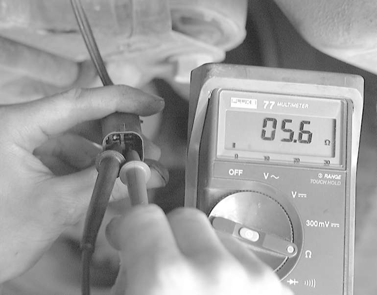
| Fig. 4: The heating circuit of the O2S sensor can
be tested with a DMM set to measure resistance
|
- Perform a visual inspection of the connector to ensure
it is properly engaged and all terminals are straight, tight and free
from corrosion or damage.
- Disengage the sensor pigtail connector from the vehicle
harness connector.
-
Using a DVOM set to read resistance (ohms), attach 1 DVOM test lead
to the HPWR terminal, and the other lead to the HGND terminal,
of the sensor pigtail connector, then observe the resistance readings.
- If there is no continuity between the HPWR
and HGND terminals, the sensor is defective. Replace it with a
new one and retest.
-
If there is continuity between the 2 terminals, but the resistance
is greater than approximately 20 ohms, the sensor is defective. Replace
it with a new one and retest.
NOTE: For the following step, the HO2S sensor
should be approximately 75°F (23°C) for the proper resistance values.
- If there is continuity between the 2 terminals
and it is less than 20 ohms, the sensor is probably not defective. Because
of the large diversity of engine control systems used in vehicles today,
O2S sensor heating circuit resistance specifications change often. Generally,
the amount of resistance an O2S sensor heating circuit should exhibit
is between 2-9 ohms. However, some manufacturer's O2S sensors may show
resistance as high as 15-20 ohms. As a rule of thumb, 20 ohms of resistance
is the upper limit allowable.
- Turn the engine OFF, remove the DVOM and all
associated jumper wires. Reattach the vehicle harness connector to the
sensor pigtail connector.
- Clear any DTC's present in the engine control computer
memory, as necessary.
NOTE: Utilize one of the in-vehicle tests before performing
this test.
This test is designed to test an O2S sensor which does not seem to fluctuate
fully beyond 400-700 mV. The sensor is to be secured in a table-mounted
vise.
CAUTION
This test can be very dangerous. Take the necessary precautions when working
with a propane torch. Ensure that all combustible substances are removed
from the work area and have a fire extinguisher ready at all times. Be
sure to wear the appropriate protective clothing as well.
-
Remove the O2S sensor.
NOTE: Perform a visual inspection of the sensor. Black
sooty deposits may indicate a rich air/fuel mixture, brown deposits may
indicate an oil consumption problem, and white gritty deposits may indicate
an internal coolant leak. All of these conditions can destroy a new sensor
if not corrected before installation.
- Position the sensor in a vise so that the vise holds
the sensor by the hex portion of its case.
- Attach 1 lead of a DVOM set to read DC millivoltages
to the sensor case and the other lead to the SOUT terminal of the
sensor pigtail connector.
-
Carefully use a propane torch to heat the tip (and ONLY the tip) of
the sensor. Once the sensor reaches close to normal operating temperature
range, alternately heat the sensor up and allow it to cool down; the sensor
output voltage signal should change with the temperature change.
NOTE: This may also clean a sensor covered with a
heavy coat of carbon.
- If the sensor voltage does not change with the fluctuation
in temperature, replace the sensor with a new one. Install the new sensor
and perform one of the in-vehicle tests to rule out additional fuel management
system faults.