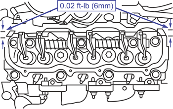
To Remove:
- Disconnect the negative battery cable and the spark plug wires.
- Drain the cooling system.
- Disconnect the crankcase vent tube, the upper radiator hose, and the electrical connectors for the mass airflow (MAF) sensor and the generator.
- Disconnect the heater water hose.
- Remove the accelerator cable snow shield.
- Disconnect the speed control actuator cable and the vacuum line.
- Remove the valve cover and gasket.
To Install:
CAUTION
Do not use wire brushes, metal scrapers, power abrasive discs or other abrasive means to clean sealing surfaces. These tools cause scratches and gouges, which can make leak paths.
- Clean and inspect the sealing surfaces.
- Use silicone gasket and sealant in the two spots illustrated below.
| Apply silicone rubber in these locations (4.0L)

|
- Install the valve cover, gasket, and bolts. Tighten in the sequence shown. Torque to 62 in-lb (7 Nm).
| Valve cover bolt tightening sequence right side (4.0L)

|
- Connect the vacuum line and the speed control actuator cable.
- Install the accelerator cable snow shield.
- Connect the heater water hose and the electrical connectors for the MAF sensor and generator.
- Connect the upper radiator hose, the crankcase vent tube, and the spark plug wires.
- Connect the negative battery cable.
- Fill and bleed the cooling system.
To Remove:
- Disconnect the negative battery cable.
- Remove the upper intake manifold, the dipstick tube, and the valve cover and gasket.
To Install:
NOTE: Clean and examine all of the mating surfaces.
- Apply a bead of silicone gasket and sealant in the two places shown below.
| Apply silicone rubber in these locations (4.0L)

|
- Install the valve cover, gasket, and bolts. Tighten according to the sequence shown. Torque to 62 in-lb (7 Nm).
| Valve cover bolt tightening sequence left side (4.0L)

|
- Install dipstick tube. Torque to 17 ft-lb (23 Nm).
- Install the upper intake manifold.

