NOTE: If equipped with an air bag or anti-theft coded radio,
disable the air bag system and obtain the anti-theft codes before proceeding.
- Disconnect the negative battery cable.
- Drain the engine coolant into a clean container for reuse.
- Remove or disconnect the following:
- Heater hoses from the heater core
- Transmission selector lever or knob
- Center console
- Steering wheel
- Upper and lower steering column covers
- Combination switch
- Instrument meter hood
- Instrument cluster assembly
- Speedometer cable
- Heater ducts
- Instrument housing lower panels
- Glove box assembly
- Heater control switch and cables
- Header and the side trim, if required
- Center cap, the side covers and the center bracket bolts on the instrument
panel
- Steering shaft bolts
- Any necessary wire harness connectors
- Instrument panel
- Seal plate
- Attaching nuts
- Heater unit
- Attaching clips on the heater unit and separate the assembly
- Heater core
To install:
- Install or connect the following:
- Heater core into the heater unit
- Heater case halves with the clips
- Heater unit
- Seal plates
- Instrument panel
- Wiring harness connectors
- Steering shaft bolts
- Center cap, the side covers and the center bracket bolts on the instrument
panel
- Header and side trim, if removed.
- Heater control switch and cables
- Glove box assembly
- Instrument housing lower panels
- Heater ducts
- Speedometer cable
- Instrument cluster and meter hood assembly
- Upper and lower steering column covers
- Steering wheel
- Center console and the shift lever or knob
- Heater core hoses
- Negative battery cable
- Refill the cooling system.
- Operate the engine to normal operating temperatures; then, check the climate
control operation and check for leaks.
- Disconnect the negative battery cable.
CAUTION
After disconnecting the battery, wait for more than 1 minute for the SAS
to deplete its stored energy.
- Drain the cooling system into a clean container for reuse.
- Disconnect the heater hoses from the heater core.
- Discharge and recover the air conditioning system refrigerant.
- Place the wheel in the straight-ahead position and turn the ignition switch
to LOCK.
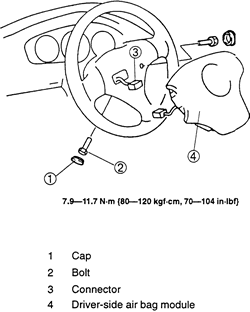
- At the driver's side, remove the SAS module and the steering wheel by removing
or disconnecting the following:
- Cover clips at both sides of the steering wheel
- Steering wheel-to-SAS module bolts
- SAS module from the steering wheel and disconnect the electrical connector
- Steering wheel-to-column nut
- Steering wheel from the steering column using a suitable puller
- At the passenger's side, remove the SAS module by removing or disconnecting
the following:
- Glove compartment and the glove compartment cover
- SAS module-to-dash bolts
- SAS module and disconnect the electrical connector
- Remove the console by removing or disconnecting the following:
- Shift lever knob, if equipped with a manual transmission
- Console's cover
- Console-to-chassis screws and console
- Remove the combination switch by removing or disconnecting the following:
- Steering column cover
- Electrical connectors and remove the combination switch-to-steering
column bolts and the combination switch
- Remove the instrument cluster by:
- Meter hood
- Instrument cluster-to-dash panel screws
- Electrical connectors and remove the instrument cluster
- Remove or disconnect the following:
- Lower panel
- Hood release cable installation nut
- Side wall trim
- "A" pillar trim at both sides
- Side panel
- Antenna connector
- Blower motor and heater unit electrical connectors, if equipped with
the wire-type climate control unit
- Electrical connectors and the bolts
- Dashboard-to-chassis bolts
- Dashboard from the vehicle with the help of an assistant
- Passenger's side lower panel
- Air intake wire from the climate control unit
- Air conditioning refrigerant lines from the evaporator. Discard the
O-rings
- Evaporator electrical connector(s)
- Evaporator housing
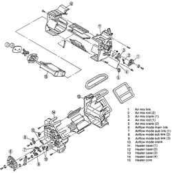
- Disassemble the heater housing and remove the heater core.
| Fig. 1: Exploded view of the SAS module and the steering
wheel assembly-1999-00 Protege
|
| Fig. 2: Exploded view of the passenger's side SAS
module-1999-00 Protege

|
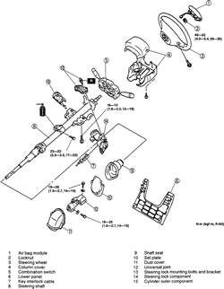
| Fig. 3: Exploded view of the steering column assembly-1999-00
Protege
|
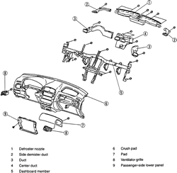
| Fig. 4: Exploded view of the dashboard assembly-1999-00
Protege
|
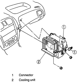
| Fig. 5: View of the evaporator housing assembly-1999-00
Protege
|
| Fig. 6: Exploded view of the heater housing assembly-1999-00
Protege
|
To install:
- Install the heater core and assemble the heater housing.
- Install or connect the following:
- Evaporator housing
- Evaporator electrical connector(s)
- Air conditioning refrigerant lines to the evaporator using new O-rings
- Air intake wire to the climate control unit
- Passenger's side lower panel
- Dashboard to the vehicle with the help of an assistant
- Dashboard-to-chassis bolts
- Electrical connectors and the bolts
- Blower motor and heater unit electrical connectors, if equipped with
the wire-type climate control unit
- Antenna connector
- Side panel
- A-pillar trim at both sides
- Side wall trim
- Hood release cable installation nut
- Lower panel
- Install the instrument cluster by installing or connecting the following:
- Instrument cluster and connect the electrical connectors
- Instrument cluster-to-dash panel screws
- Meter hood
- Install the combination switch by installing or connecting the following:
- Electrical connectors and install the combination switch-to-steering
column bolts and the combination switch
- Steering column cover
- Install the console by installing or connecting the following:
- Console and the console-to-chassis screws
- Console's cover
- Shift lever knob, if equipped with a manual transmission
- At the passenger's side, install the SAS module by installing or connecting
the following:
- SAS module and connect the electrical connector
- SAS module-to-dash bolts
- Glove compartment and the glove compartment cover
- At the driver's side, install the SAS module and the steering wheel by installing
or connecting the following:
- Steering wheel-to-column nut
- SAS module from the steering wheel and connect the electrical connector
- Steering wheel-to-SAS module bolts
- Cover clips at both sides of the steering wheel
- Connect the heater hoses to the heater core.
- Refill the cooling system.
- Connect the negative battery cable.
- Evacuate, charge and leak test the air conditioning system.
- Operate the engine to normal operating temperatures; then, check the climate
control operation and check for leaks.


