- Before servicing the vehicle, refer to the precautions in the beginning
of this section.
- Relieve the fuel system pressure.
- Drain the cooling system.
- Properly discharge the A/C system.
- Remove or disconnect the following:
- Negative battery cable
- Loosen the water pump pulley bolts
- Drive belt
- Water pump pulley
- Fan and clutch assembly
- Intake manifolds
- Ignition wires from the spark plugs
- Spark plugs
- Oil level indicator tube
- Exhaust Gas Recirculation (EGR) valve to the exhaust manifold tube
- Valve cover
- Engine control wiring from the A/C compressor
- A/C compressor mounting bracket with the power steering pump attached
and move them aside
- Engine control sensor wiring from the alternator
- Lower radiator hose
- Water pump inlet tube
- Upper radiator hose
- Alternator
- Alternator mounting bracket
- Ignition wire and bracket
- Outer timing belt cover
- Timing belt
- Exhaust manifold
- Cylinder head and discard the bolts and the gasket
To install:
- Clean the mating surface where the cylinder head attaches to the engine.
- Install a new gasket and the cylinder head.
NOTE: Refer to Section 1 of this manual for the cylinder
head torque sequence illustration. The illustration is located after the
Torque Specification Chart.
- Torque the new cylinder head bolts in stages as follows:
- Step 1: 51 ft. lbs. (70 Nm).
- Step 2: An additional 51 ft. lbs. (70 Nm).
- Step 3: Plus and additional 90 degrees.
- Install or connect the following:
- Exhaust manifold. Torque the bolts to 15 ft. lbs. (20 Nm) plus an additional
30 ft. lbs. (40 Nm).
- Timing belt tensioner and timing belt
- Timing belt cover
- Ignition wires and coil
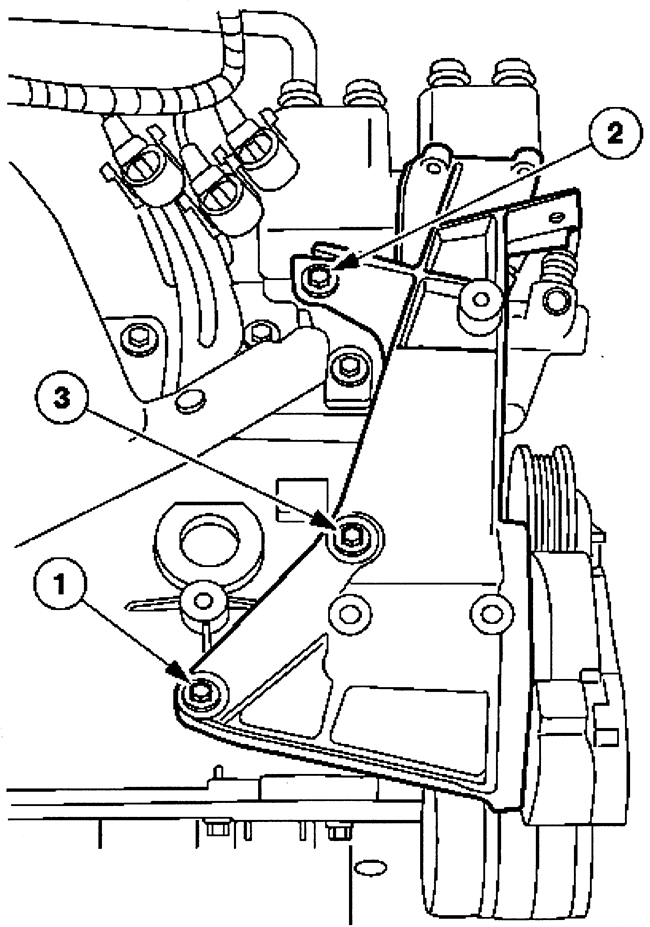
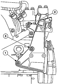
- Install the alternator bracket. Torque the bolts in 4 stages as follows:
- Step 1: Hand tighten bolt No. 1.
- Step 2: Torque bolt No. 2 to 40 ft. lbs. (55 Nm).
- Step 3: Torque bolt No. 3 to 40 ft. lbs. (55 Nm).
- Step 4: Torque bolt No. 1 to 40 ft. lbs. (55 Nm).
| Fig. 1: Alternator bracket bolt tightening sequence
2.3L–2.5L engines
|
- Install or connect the following:
- Water pump inlet tube with a new O-ring to the water pump. Torque the
bolts to 89 inch lbs. (10 Nm).
- Lower radiator hose
- Alternator
- Upper radiator hose and heater hose
- A/C compressor mounting bracket with the power steering pump attached.
Torque the bolts to 40 ft. lbs. (55 Nm).
- A/C compressor. Torque the bolts to 20 ft. lbs. (28 Nm).
- Water pump pulley and fan clutch. Hand tighten the bolts
- Drive belt. When the belt is positioned properly, torque the fan clutch
bolts to 16 ft. lbs. (23 Nm).
- Fan shroud
- Sparks plugs
- Oil level indicator tube
- Engine control sensor wiring
- Upper intake manifold
- EGR valve to the exhaust manifold tube. Torque the bolts to 34 ft. lbs.
(47 Nm).
- EGR transducer to the rear of the engine
- Negative battery cable
- Recharge the A/C system.
- Filling the cooling system.
- Start the vehicle and check for leaks, repair if necessary.
NOTE: On 1997 Aerostar models, it is necessary to remove the
engine to perform this procedure. On other models, it may be easier to remove
the engine from the vehicle. If removing the engine, refer to the engine removal
procedure in this section.
- Before servicing the vehicle, refer to the precautions in the beginning
of this section.
- Evacuate the A/C system.
- Drain the cooling system.
- Drain the engine oil.
- Remove or disconnect the following:
- Negative battery cable
- Lower intake manifold
- A/C compressor
- Alternator
- Power steering pump
- Alternator mounting bracket
- A/C compressor mounting bracket
- Exhaust manifolds
- Cylinder head and discard the bolts and gasket
To install:
NOTE: The "V" in the cylinder head gasket must face the
front of the engine.
- Clean the mating surfaces where the head attaches to the engine.
- Install a new cylinder head gasket and the cylinder head to the engine.
NOTE: Refer to Section 1 of this manual for the cylinder
head torque sequence illustration. The illustration is located after the
Torque Specification Chart.
- Torque the new cylinder head bolts in stages as follows:
- Step 1: 59 ft. lbs. (80 Nm).
- Step 2:Loosen the bolts one full turn.
- Step 3:40 ft. lbs. (55 Nm).
- Step 4: 63 ft. lbs. (85 Nm).
- Install or connect the following:
- Lower intake manifold
- Exhaust manifold
- A/C compressor mounting bracket. Torque the bolts to 44 ft. lbs. (66
Nm).
- Alternator mounting bracket
- Power steering pump
- Alternator
- A/C compressor
- Negative battery cable
- Fill the engine with clean oil
- Fill the cooling system.
- recharge the A/C system
- Start the vehicle and check for leaks, repair if necessary.
NOTE: New cylinder head bolts must be used when installing
the cylinder head on the 4.0L OHV engine.
- Before servicing the vehicle, refer to the precautions in the beginning
of this section.
- Relieve the fuel system pressure.
- Evacuate the A/C system.
- Drain the cooling system.
- Drain the engine oil.
- Remove or disconnect the following:
- Negative battery cable
- Drive belt
- Separate the A/C manifold tube from the A/C compressor
- A/C compressor electrical connectors
- A/C compressor mounting bracket and move it aside
- Alternator electrical connectors
- Heater hose and move it aside
- Alternator mounting bracket
- Lower intake manifold
- Both exhaust manifolds
- Gradually loosen the rocker arm shafts and remove them.
- Matchmark the position of the push rods and remove them
- Cylinder head and gasket
To install:
To install:
- Clean the mating surface where the cylinder head attaches to the engine.
- Install a new cylinder head gasket and the cylinder head to the engine.
NOTE: Refer to Section 1 of this manual for the cylinder
head torque sequence illustration. The illustration is located after the
Torque Specification Chart.
- Torque the new cylinder head bolts in sequence as follows:
- Step 1: 25 ft. lbs. (34 Nm).
- Step 2: 53 ft. lbs. (72 Nm).
- Step 3: Plus an additional 90 degrees.
- Install or connect the following:
- Push rods
- Rocker arm shafts gradually. Torque the bolts to 24 ft lbs. (33 Nm)
plus an additional 90 degrees
- Exhaust manifolds
- Lower intake manifold
- Alternator bracket. Torque the bolts to 35 ft. lbs. (47 Nm).
- Heater hose retaining clip
- Alternator electrical connectors
- A/C compressor mounting bracket. Torque the bolts to 35 ft. lbs. (47
Nm).
- A/C compressor electrical connectors
- A/C manifold tube to the A/C compressor
- Drive belt
- Negative battery cable
- Fill the cooling system.
- Fill the engine with clean oil. A filter replacement is also recommended.
- Recharge the A/C system.
NOTE: When the battery has been disconnected and reconnected,
some abnormal drive symptoms may occur while the Powertrain Control Module
(PCM) relearns its adaptive strategy. The vehicle may need to be driven
about 10 miles (16 km) or more to relearn the strategy.
- Start the engine and check for leaks.