- On all vehicles, when trouble shooting the wiper system, test the motor
first, then work back towards the switch to test the interval governor or
module (depending on the vehicle), power circuits and the switch itself.
- In most of the tests, a volt-ohmmeter is required, although a test light
can also be useful. For testing the motor, a 0–15 amp DC ammeter is
required.
- When the test calls for a voltage check, the ignition switch must be in
the ON position.
- When testing for continuity or resistance values, turn the ignition switch
to the OFF position and/or disconnect the negative battery
cable.
- Improper or careless testing can cause permanent damage to the vehicle's
electronic circuits and to test equipment. Carefully follow the test equipment
manufacturer's instructions.
- Disconnect the positive cable from the battery.
- Remove the wiper motor linkage and electrical connectors from the windshield
wiper motor.
NOTE: If the electrical connector is not accessible, the
motor may need to be removed.
- Using a suitable starting charging tester, connect the power lead (green)
of the tester to the positive battery terminal.
- Connect the positive (red) lead from the tester to the low speed connection
and high speed connection at the connector plug.
- The draw should be no more than 3.0 amps at either speed. Repairs to the
motor itself are not possible.
| Fig. 1: Wiper motor current draw test — Navajo,
B2300, B3000, B4000

|
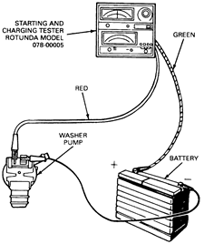
- Attach the leads of a digital volt/ohmmeter or suitable starting charging
tester as shown. The current draw should not exceed 4 amps or be less than
1.7 amps while the windshield washer pump is pumping fluid.
| Fig. 2: Wiper washer pump current draw test

|
The front wipers and washers use the same 6 amp circuit breaker (B-Series),
8.25 amps (Navajo), located in the fuse panel. Two separate tests are necessary
to check for correct circuit breaker operation.
- Remove the circuit breaker from the fuse panel.
- Using a suitable volt-amp tester, touch the test leads together and adjust
the current draw until it equals the circuit breaker rating.
- Connect the test leads to the circuit breaker, hold the current reading
on the ammeter at the rated current and leave it connected for 10 minutes.
- If the circuit breaker opens during the 10 minutes, replace the circuit
breaker.
- Touch the tester's leads together and adjust the current draw until it is
twice the rated current.
- Connect the circuit breaker to the tester and hold the current rating on
twice the rated current.
- The current reading on the ammeter should drop to 0 within 30 seconds.
- If it takes longer than 30 seconds for the ammeter to drop to 0 (circuit
breaker to open), replace the circuit breaker.
If interval operation is unsatisfactory, first check the motor current draw,
the control switch and all the connecting wires for continuity. If the motor,
switch and connecting wires are OK, replace the electronic governor.
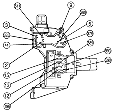
| Fig. 3: Turn signal/wiper/washer switch terminal locations
for switch continuity test — B2300, B3000, B4000 and Navajo

|
- Check for an open circuit with the wiper/washer switch OFF.
- Turn the washer OFF.
- Check for an open circuit between Circuit 993 and Circuit 590.
- Check for an closed circuit with the wiper/washer switch ON.
- Turn the washer ON.
- Check for continuity between Circuit 993 and Circuit 590.
- Check for an open circuit/resistance with the wiper on OFF and
the washer on OFF.
- Turn the wiper OFF.
- Turn the washer OFF.
- Check for and open circuit between circuit 589 and circuit 590.
- Measure the resistance between circuit 993 and circuit 590. The correct
resistance should be 103,000 ohms.
- Measure the resistance between circuit 993 and circuit 589. The correct
resistance should be 47,600 ohms.
- Check for an open circuit/resistance with the wiper on LOW and
the washer on OFF.
- Turn the wiper LOW.
- Turn the washer OFF.
- Check for and open circuit between circuit 589 and circuit 590.
- Measure the resistance between circuit 993 and circuit 590. The correct
resistance should be 3,300 ohms.
- Measure the resistance between circuit 993 and circuit 589. The correct
resistance should be 4,100 ohms.
- Check for an open circuit/resistance with the wiper on HIGH and
the washer on OFF.
- Turn the wiper HIGH.
- Turn the washer OFF.
- Check for and open circuit between circuit 993 and circuit 589.
- Measure the resistance between circuit 993 and circuit 590. The correct
resistance should be 3,300 ohms.
- Check for an open circuit/resistance with interval at MAXIMUM DELAY.
- Turn the wiper interval delay to the maximum setting.
- Check for and open circuit between circuit 589 and circuit 590.
- Measure the resistance between circuit 993 and circuit 590. The correct
resistance should be 103,300 ohms.
- Check for an open circuit/resistance with interval at MINIMUM DELAY.
- Turn the wiper interval delay to the minimum setting.
- Check for and open circuit between circuit 589 and circuit 590.
- Measure the resistance between circuit 993 and circuit 590. The correct
resistance should be 3,300 ohms.
- Measure the resistance between circuit 993 and circuit 589. The correct
resistance should be 11,300 ohms.


