- Before servicing the vehicle, refer to the precautions in the beginning of this section.
- With the vehicle in neutral, place it on a hoist.
- Properly relieve the fuel system pressure.
- Drain the cooling system.
- Remove the intake manifold.
- Remove the cooling fan shroud.
- Remove the accessory drive belt.
- Remove the left valve cover then the right valve cover.
- Disconnect the generator.
- Remove the accessory drive belt tensioner.
- Remove the bolts and the generator mounting bracket and generator as an assembly.
- Disconnect the engine wiring harness and detach the harness retainers.
- Detach the engine wiring harness retainer.
- Disconnect the crankshaft position (CKP) sensor.
- Disconnect the wiring harness retainers.
- Disconnect the coolant temperature indicator sender unit and the engine coolant temperature (ECT) sensor.
NOTE: The coolant bypass hose will be removed with the thermostat housing.
- Move the coolant bypass hose clamp off the coolant pump outlet.
- Remove the bolts and the thermostat housing and coolant bypass hose.
- Remove the bolt and the wiring harness retainer.
- Remove the bolts and position the accessory bracket aside.
- Disconnect the wiring harness casing from the left cylinder head.
- Remove the bolt and the oil level indicator tube.
- Using commercially-available spark plug boot pliers, disconnect the left-hand spark plug wires from the spark plugs.
- Disconnect the fuel pulse damper vacuum hose.
- Remove the fuel injection supply manifold. Keep the four bolts, the supply manifold, and the fuel injectors as an assembly.
NOTE: Mark all of the roller followers to ensure they are installed in their original position during reassembly.
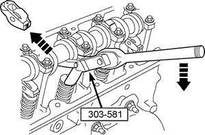
- Use the valve spring compressor tool (303-581), or an equivalent, to remove the roller followers.
| Valve spring compressor tool

|
NOTE: The crankshaft holding tool (303-573), or an equivalent, must be installed on the damper and should contact the engine block. This positions the engine at top dead center.
- Using the crankshaft holding tool (303-573), set the No. 1 piston to top dead center.
- Remove the right fender well splash shield.
- Remove the right camshaft tensioner.
- Remove the right exhaust manifold.
- Remove the bolt and bracket.
CAUTION
The right-hand camshaft sprocket bolt is a left-hand threaded bolt.
NOTE: If necessary, use the camshaft gear torque adapter (303-565), or an equivalent, to remove camshaft sprocket bolt.
- Remove the right camshaft sprocket bolt using the camshaft gear removal tool (303-575), or an equivalent.
- Remove the chain guide bolt.
CAUTION
Remove the camshaft sprocket to prevent breaking the cassette and to gain clearance to remove the cylinder head.
NOTE: Hold the chain and cassette with a rubber band to aid in removal and prevent the chain from falling into the cylinder block.
- Remove the right-hand camshaft sprocket from the cassette.
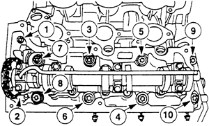
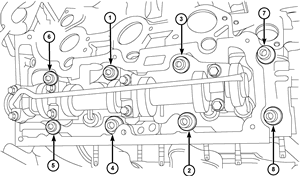
- Remove the eight 12 mm (0.47 in.) bolts and the two 8 mm (0.31 in.) bolts in the sequence shown, and remove the right cylinder head. Next, discard the head gasket and cylinder head bolts.
| The correct cylinder head bolt loosening sequence must be used to prevent warpage-4.0L engine

|
- Clean the gasket mating services.
- Position the cylinder head gasket and the cylinder head.
NOTE: Cylinder head bolts are torque-to-yield designed, so new bolts must be installed.
- Install the 12 mm (0.47 in.) bolts and tighten in the following sequence:
- Step 1: Tighten to 9 ft-lb (12 Nm).
- Step 2: Tighten to 18 ft-lb (25 Nm).
- Install the two 8 mm (0.31 in.) bolts.
- Torque to 24 ft-lb (32 Nm).
- Tighten the eight 12 mm (0.47 in.) bolts in the following sequence:
- Step 1: Tighten the bolts 90 degrees.
- Step 2: Tighten the bolts an additional 90 degrees.
- Position the right camshaft sprocket in the chain and install it on the camshaft.
CAUTION
The camshaft sprocket must turn freely on the camshaft. DO NOT tighten the bolt.
- Install the right camshaft sprocket bolt.
- Install the chain guide bolt.
- Torque to 89 in-lb (10 Nm).
- Install the bracket and bolt.
- Torque to 9 ft-lb (12 Nm).
- Install the left exhaust manifold.
CAUTION
The right-hand camshaft sprocket bolt is a left-hand threaded bolt.
NOTE: Use the camshaft gear torque adapter (303-565), or an equivalent, to loosen the camshaft sprocket bolt. If necessary, loosen the right camshaft sprocket bolt with the camshaft gear removal tool (303-575), or an equivalent.
NOTE: Notice that the camshaft timing slots are off-center.
- Position the camshaft timing slots below the center line of the camshaft and install the camshaft holding tool adapter (303-576) and the camshaft holding tool (303-577), or equivalent tools, on the front of the right cylinder head.
- Remove the right fender well splash shield.
- Remove the right camshaft tensioner.
NOTE: Leave the top two camshaft gear holding tool (303-564) clamp bolts loose.
- Install the camshaft gear holding tool (303-564) and the camshaft gear holding tool adapter (303-578), or equivalent tools, on the rear of the right cylinder head.
- Install the timing chain tensioner (303-571), or an equivalent tool.
CAUTION
The right-hand camshaft sprocket bolt is a left-hand threaded bolt.
NOTE: Use the camshaft gear torque adapter (303-565), or an equivalent, to tighten the camshaft sprocket bolt.
- Next, tighten the camshaft gear holding tool (303-564) top two clamp bolts to 89 in. lb. (10 Nm).
- Tighten the camshaft bolt to 45 ft. lb. (61 Nm).
- Install the right camshaft tensioner.
- Torque to 32 ft-lb (44 Nm).
- Install the right fender well splash shield.
- Remove the left camshaft tensioner.
- If necessary, loosen the left camshaft sprocket bolt.
NOTE: Leave the top two camshaft gear holding tool (303-564) clamp bolts loose.
- Install the camshaft gear holding tool (303-564) and the camshaft gear holding tool adapter (303-578) special tools on the front of the left cylinder head.
NOTE: The camshaft timing slots are off-center.
- Position the camshaft timing slots below the center line of the camshaft and install the camshaft holding tool (303-577) and the camshaft holding tool adapter (303-576), or equivalent tools, on the rear of the left cylinder head.
- Install the timing chain tensioner (303-571), or equivalent tool.
- Next, tighten the camshaft gear holding tool (303-564) top two clamp bolts to 89 in-lb (10 Nm).
- Tighten the camshaft bolt to 63 ft-lb (85 Nm).
- Install the left-hand camshaft tensioner.
- Torque to 32 ft-lb (44 Nm).
NOTE: Install each roller follower in its original position.
- Using the (303-581) valve spring compressor, or equivalent tool, install the camshaft roller followers.
- Install the fuel injection supply manifold and fuel injectors as an assembly.
- Torque to 17 ft-lb (23 Nm).
- Install the fuel supply tube to the fuel manifold.
- Torque to 53 in-lb (6 Nm).
- Connect the fuel pulse damper vacuum hose.
- Connect the left-hand spark plug wires to the spark plugs.
- Install the oil level indicator tube and the bolt.
- Torque to 89 in-lb (10 Nm).
- Connect the wiring harness casing to the left cylinder head.
- Install the accessory bracket and the bolts.
- Torque to 31 ft-lb (42 Nm).
- Position the wiring harness clip and install the bolt.
- Torque to 15 ft-lb (20 Nm).
- Install the thermostat housing and the bolts with the coolant bypass hose.
- Torque to 8 ft-lb (11 Nm).
- Connect the coolant bypass hose clamp.
- Connect the water temperature indicator sender unit and the engine coolant temperature (ECT) sensor.
- Connect the electrical harness retainers.
- Connect the crankshaft position (CKP) sensor.
- Attach the engine wiring harness retainer.
- Attach the wiring harness retainers and connect the electrical connector.
- Position the generator mounting bracket and generator assembly and install the bolts.
- Torque to 31 ft-lb (42 Nm).
- Install the accessory drive belt tensioner.
- Torque to 35 ft-lb (47 Nm).
- Connect the generator.
- Torque to 71 in-lb (8 Nm).
- Install the right valve cover, then the left valve cover.
- Install the accessory drive belt, then the cooling fan shroud.
- Install the intake manifold.
- Fill and bleed the cooling system.
- Connect the negative battery cable.
- Change the engine oil and filter.
- Start the engine and check for leaks, repair if necessary.
- Thoroughly clean all gasket mating surfaces. Remove all traces of old gasket material, oil, grease or dirt.
- Ensure that the rubber band is holding the right-hand chain to the cassette.
- Install a new head gasket and the cylinder head.
NOTE: Cylinder head bolts are torque-to-yield designed, so new bolts must be installed.
- Install the 12 mm (0.47 in.) bolts and tighten in the following sequence:
- Step 1: Tighten to 9 ft-lb (12 Nm).
- Step 2: Tighten to 18 ft-lb (25 Nm).
- Install the two 8 mm (0.31 in.) bolts.
- Torque to 24 ft-lb (32 Nm).
- Tighten the eight 12 mm (0.47 in.) bolts in the following sequence:
- Step 1: Tighten the bolts 90 degrees.
- Step 2: Tighten the bolts an additional 90 degrees.
- Install the left camshaft sprocket.
| The correct cylinder head bolt tightening sequence must be used

|
CAUTION
The camshaft sprocket must turn freely on the camshaft. DO NOT tighten the bolt.
- Install the camshaft sprocket bolt.
- Install the chain guide bolt.
- Torque to 9 ft-lb (12 Nm).
- Install the ground strap and bolt.
- Torque to 18 ft-lb (25 Nm).
- Install the engine wiring harness pin-type retainer.
- Install the left exhaust manifold.
CAUTION
The right-hand camshaft sprocket bolt is a left-hand threaded bolt.
NOTE: Use the camshaft gear torque adapter (303-565), or an equivalent, to loosen the camshaft sprocket bolt. If necessary, loosen the right-hand camshaft sprocket bolt with the camshaft gear removal tool (303-575), or an equivalent.
NOTE: Notice that the camshaft timing slots are off-center.
- Position the camshaft timing slots below the center line of the camshaft and install the camshaft holding tool adapter (303-576) and the camshaft holding tool (303-577), or equivalent tools, on the front of the right-hand cylinder head.
- Remove the right fender well splash shield.
- Remove the right camshaft tensioner.
NOTE: Leave the top two camshaft gear holding tool (303-564) clamp bolts loose.
- Install the camshaft gear holding tool (303-564) and the camshaft gear holding tool adapter (303-578), or equivalent tools, on the rear of the right cylinder head.
- Install the timing chain tensioner (303-571), or an equivalent tool.
CAUTION
The right-hand camshaft sprocket bolt is a left-hand threaded bolt.
NOTE: Use the camshaft gear torque adapter (303-565), or an equivalent, to tighten the camshaft sprocket bolt.
- Next, tighten the camshaft gear holding tool (303-564) top two clamp bolts to 89 in. lb. (10 Nm).
- Tighten the camshaft bolt to 45 ft. lb. (61 Nm).
- Install the right-hand camshaft tensioner.
- Torque to 32 ft-lb (44 Nm).
- Install the right-hand fender well splash shield.
- Remove the left camshaft tensioner.
- If necessary, loosen the left camshaft sprocket bolt.
NOTE: Leave the top two camshaft gear holding tool (303-564) clamp bolts loose.
- Install the camshaft gear holding tool (303-564) and the camshaft gear holding tool adapter (303-578) special tools on the front of the left cylinder head.
NOTE: The camshaft timing slots are off-center.
- Position the camshaft timing slots below the center line of the camshaft and install the camshaft holding tool (303-577) and the camshaft holding tool adapter (303-576), or equivalent tools, on the rear of the left cylinder head.
- Install the timing chain tensioner (303-571), or equivalent tool.
- Next, tighten the camshaft gear holding tool (303-564) top two clamp bolts to 89 in-lb (10 Nm).
- Tighten the camshaft bolt to 63 ft-lb (85 Nm).
- Install the left camshaft tensioner.
- Torque to 32 ft-lb (44 Nm).
NOTE: Install each roller follower in its original position.
- Using the (303-581) valve spring compressor, or equivalent tool, install the camshaft roller followers.
- Install the fuel injection supply manifold and fuel injectors as an assembly.
- Torque to 17 ft-lb (23 Nm).
- Install the fuel supply tube to the fuel manifold.
- Torque to 53 in-lb (6 Nm).
- Connect the fuel pulse damper vacuum hose.
- Connect the left spark plug wires to the spark plugs.
- Install the oil level indicator tube and the bolt.
- Torque to 89 in-lb (10 Nm).
- Connect the wiring harness casing to the left cylinder head.
- Install the accessory bracket and the bolts.
- Torque to 31 ft-lb (42 Nm).
- Position the wiring harness clip and install the bolt.
- Torque to 15 ft-lb (20 Nm).
- Install the thermostat housing and the bolts with the coolant bypass hose.
- Torque to 8 ft-lb (11 Nm).
- Connect the coolant bypass hose clamp.
- Connect the water temperature indicator sender unit and the engine coolant temperature (ECT) sensor.
- Connect the electrical harness retainers.
- Connect the crankshaft position (CKP) sensor.
- Attach the engine wiring harness retainer.
- Attach the wiring harness retainers and connect the electrical connector.
- Position the generator mounting bracket and generator assembly and install the bolts.
- Torque to 31 ft-lb (42 Nm).
- Install the accessory drive belt tensioner.
- Torque to 35 ft-lb (47 Nm).
- Connect the generator electrical connections.
- Torque to 71 in-lb (8 Nm).
- Install the right valve cover, then the left valve cover.
- Install the accessory drive belt, then the cooling fan shroud.
- Install the intake manifold.
- Fill and bleed the cooling system.
- Connect the negative battery cable.
- Change the engine oil and filter.
- Start the engine and check for leaks, repair if necessary.

