WARNING
To avoid personal injury and/or vehicle damage, refer to the service precautions at the beginning of this section.
The Engine Management System (EMS) uses several different sensors and actuators to gather and control various emissions and driveability aspects of the vehicle. These may include but are not limited to:
These sensors provide critical information to the EMS such as, barometric pressure, atmospheric pressure, intake manifold/engine vacuum, fuel tank pressures and changes as the vehicle is operated.
The EMS uses the MAP sensor on systems that have a Mass Airflow Sensor (MAF) as a backup. The EMS also uses the MAP sensor as an EGR diagnostic device and as an engine load verification device. The EMS system uses this information to calculate engine load and EGR flow rates. The EMS uses speed-density calculations (non-mass airflow sensor systems) to determine the required amount of fuel delivery.
The EMS uses a barometric (BARO) sensor on some vehicles to help compensate for barometric changes at different altitudes. Barometric pressure changes with the weather and with altitude. Essentially the density and humidity associated with the air around the vehicle is monitored so the EMS can adjust for varying conditions. Since barometric pressure affects the density of the air entering the engine and ultimately the air/fuel ratio, some engine management systems use a barometric pressure sensor so that the spark advance and EGR flow can be regulated to control emissions more precisely.
The Fuel Tank Pressure (FTP) sensor is part of the evaporative emissions system. The engine control system monitors gasoline vapor pressures in the fuel tank to determine fuel tank sealing. The FTP sensor can be used in conjunction with an EVAP vent valve and an EVAP canister purge valve.
When ambient temperatures are above 68° Fahrenheit the gasoline in the fuel tank vaporizes increasing fuel tank pressure. The FTP sensor is used to determine how much evaporative pressure is being maintained in fuel tank. This is a test for gross evaporative emissions leaks.
Some vehicles will route a small amount of engine vacuum through the canister purge valve to the fuel tank. When both the canister purge valve and vent solenoid valve are closed the vacuum is trapped between the fuel tank and canister purge valve. The fuel tank pressure sensor signals the EMS that the vacuum is present. The vacuum in the system should reach a certain level and remain for a pre-determined amount of time. This is used to test for minute system pressure leaks.
The engine coolant temperature (ECT) sensor is a variable resistor that measures the temperature of the engine coolant. When the engine coolant temperature is low, the sensor resistance is high. When the engine coolant temperature is high, the sensor resistance is low. The Engine Coolant Temperature Sensor (ECT) input to the PCM is a primary input for calculation strategies, fuel delivery control and spark timing. The ECT is also used to determine loop status timer requirements (inside of PCM) and to support cooling fan operation. ECT failures can cause excessive rich conditions, increased injector pulse-width and retarded spark timing.
The air fuel ratio (A/F) sensor like the oxygen sensor is used by the powertrain control module to measure the amount of oxygen in the exhaust. The PCM uses this data to control the air fuel mixture in the engine. The (A/F) sensor can meter fuel more accurately than an oxygen sensor. The A/F sensor changes current output by measuring the amount of oxygen in the exhaust. The A/F sensor operates at a much higher temperature than an oxygen sensor. The PCM measures the amount of current that is output by the A/F sensor and converts this current flow data to a voltage signal. When the mixture is lean and the oxygen content is high the voltage signal will be above 3.3V. When the mixture is rich and the oxygen content is low the voltage signal will be below 3.3V. When the mixture is at 14.7 to 1 the voltage signal will be at 3.3V. The heater circuit in the A/F sensor shortens the time required for the sensor to reach operating temperature and provides a more accurate signal.
The Accelerator Pedal Position (APP) sensor contains 2 potentiometer sensors that convert the accelerator pedal position into two signals. Each sensor has three circuits a 5V reference, a signal and a low reference. The APP sensor provides the PCM with voltage signals proportional to the pedal movement. The voltage signal differs by 1 volt between the two sensors. When one APP sensor signal measures 0.5V the other TP sensor will measure 1.5V.
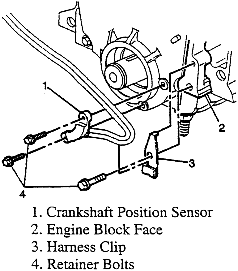
The crankshaft position (CKP) sensor generates a magnetic pulse signal when the engine is cranking or running. This signal is used by the powertrain control module (PCM) to detect the crankshaft position of each cylinder.
Engine speed is a very important input to the PCM. Crankshaft speed and position are the basis for many calculations made by the computer. Crankshaft position values are transmitted to the computer by pickup coils also known as Permanent Magnet (P/M) generators, Hall Effect sensors or optical sensors. The Crankshaft Position Sensor (CKP) also known as engine speed sensor is typically located in proximity to the crankshaft.
In addition, the PCM uses the CKP sensor in conjunction with the camshaft position sensor to calculate and perform misfire diagnostics.
| Typical crankshaft position (CKP) sensor
|
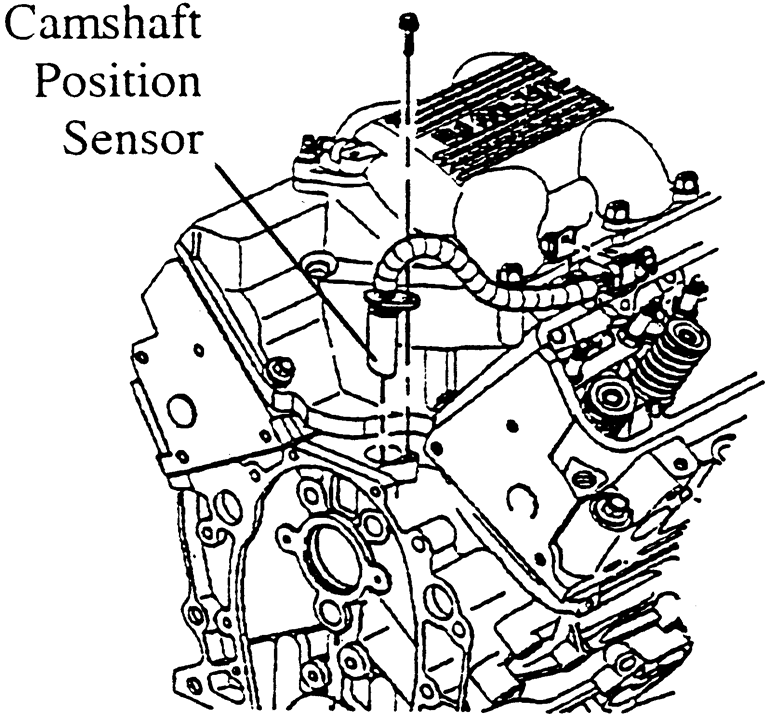
The Camshaft Position (CMP) sensor consists of a permanent magnet, yoke and coil. The CMP sensor is positioned next to the cam gear. As each cam gear tooth passes the sensor magnetic pick-up an AC voltage pulse is induced in the coil. The PCM counts the number of pulses to determine the camshaft speed. The number of pulses counted in one second is the signal frequency.
The Powertrain Control Module (PCM) uses the camshaft position sensor to manage sequential fuel injection and as part of misfire diagnosis. The PCM constantly monitors the number of pulses on the signal circuit. The PCM compares the number of camshaft sensor reference pulses and the number of crankshaft position sensor reference pulses received. If the PCM receives an incorrect number of pulses, Diagnostic Trouble Codes (DTCs) should be stored in the PCM. Some PCM systems will then default to multi-port or "gang-fire" injector operation. The camshaft position sensor signal is required to sequence the injector operation to the proper cylinder timing. If the camshaft position sensor or circuit is faulty, most engines will start. However, the PCM misfire diagnostic will likely be affected.
| Typical CMP sensor
|
The EGR valve position sensor is a potentiometer that monitors the movement of the EGR valve pintle. The EGR valve position sensor then provides the pintle position to the PCM. The EGR valve position sensor signal varies from approximately 0.50V when the valve is closed to approximately 4.5V when the valve is open.
HO 2S
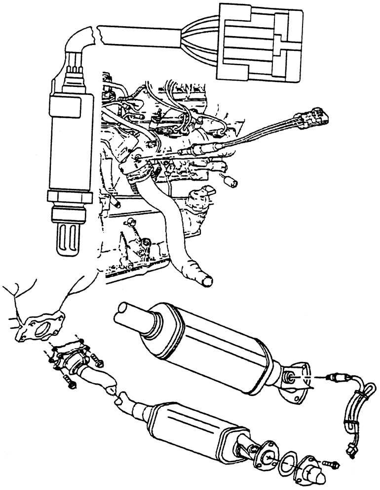
The heated oxygen sensor is used by the powertrain control module to measure the amount of oxygen in the exhaust. The PCM uses this data to control the air fuel mixture in the engine. The PCM sends a bias voltage of approximately 450 mV to the oxygen sensor. At operating temperature the oxygen sensor signal varies between 0 and 1,000 mV. When the mixture is rich the oxygen content is low and the voltage signal will remain on the high side of the 450 mV mid-range. When the mixture is lean the oxygen content is high and the voltage signal will remain on the low side below the 450 mV mid-range.
| Typical oxygen sensor
|
The oxygen sensors on later model vehicles are equipped with a heater circuit. The heater circuit in the oxygen sensor shortens the time required for the sensor to reach operating temperature and provides a more accurate signal.
Idle speed control is accomplished through the use of the Idle Air Control (IAC) motor or IAC valve in combination with ignition timing. Some applications use a second air passage and control device to provide additional air to compensate for the additional load created when the A/C compressor is running. The pintle-type IAC motor typically has a dual winding driven pintle that controls the size of a metered orifice that is part of the throttle body housing. The pintle seat will be at or near the axis of the throttle plate(s).
The Intake Air Temperature (IAT) sensor is variable temperature sensitive resistor that measures the temperature of the air in the intake system. Sensor resistance will change based on air temperature. The higher the temperature is, the lower the resistance. The Power Train Control Module (PCM) provides a reference voltage and monitors the voltage drop between a fixed value internal resistance and the sensor resistance. This is called a voltage divider circuit.
IAT sensor values are used by the PCM processor to assist with the calculation of idle speed, fuel mixture and spark advance.
Inaccurate voltages from the IAT sensor may affect pulse-width, idle quality, and tail pipe emissions. Intermittent signals may cause hesitation, stumble and surging. If an IAT sensor failure accompanies an Engine Coolant Temperature (ECT) sensor failure, cooling fan operation may also be affected.
Some manufacturers incorporate the Intake Air Temperature (IAT) sensor as part of the Mass Air Flow (MAF) sensor (Air Flow Meter).
The purpose of the Knock Sensor (KS) is to monitor pre-ignition or "engine knock" and send the signal to the PCM. The PCM responds by adjusting ignition timing until the knocking stops. The sensor works by generating a signal produced by the frequency of the knock as recorded by the piezoelectric ceramic disc inside the KS. The disc absorbs the shock waves from the knock vibration and exerts a pressure on the metal diaphragm inside the KS. This compresses the crystals inside the disc which generates a voltage signal proportional to the frequency of the knock vibration.
Mass Airflow (MAF) sensors measure the weight and rate of air moving through a passage of a known volume or size. Typically, MAF sensors utilize hot wire or thick film technology. Signals generated may be analog or digital depending on manufacturer. As more air passes through the MAF sensor, the voltage or frequency increases proportionally. The PCM uses this information to calculate injector pulse-width and spark advance. Performance issues from MAF sensor failures range from no-start conditions to stalling, hesitation, stumble and improper air/fuel mixtures. The MAF sensor values vary from 0.2V (0 gm/sec) to 4.8V (175 gm/sec).
Some manufacturers incorporate the Intake Air Temperature (IAT) sensor as part of the Mass Air Flow (MAF) sensor (Air Flow Meter).
Some manufacturers incorporate a 6.0V to 9.0V circuit from the MAF sensor to the PCM to control the MAF sensor reset signal.
The Throttle Position (TP) sensor and accelerator pedal position (APP) sensor are the only sensors sending data to the Powertrain Control Module (PCM) that the vehicle operator has direct control over. The TP sensor is a three wire potentiometer that provides an analog signal to the computer. This signal represents how far the throttle plates have opened.
The Powertrain Control Module calculates how much air should have entered the engine and compares this value with the Manifold Absolute Pressure (MAP) sensor or Mass Air Flow (MAF) sensor value. The PCM uses this information to calculate fuel delivery and ignition timing requirements.
The PCM on vehicles equipped with an electronic transmission utilize the TP sensor in combination with the MAP and MAF sensor values to determine shift schedules and torque converter clutch application.
| Typical TP sensor
|
| Missing file(s): 91174g15. |
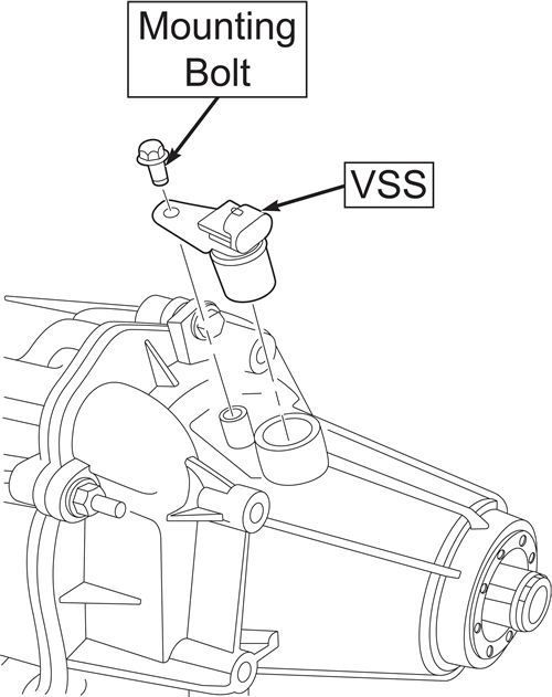
The Vehicle Speed (VSS) Sensor input is used by the PCM to determine vehicle speed. The VSS generates a signal that increases in frequency proportionate to vehicle speed. The PCM has a base frequency stored in memory for a distance of one mile. By comparing the input and stored value, the PCM calculates vehicle speed.
VSS types include: photo-optic, permanent magnet generators or hall effect technology. The PCM may use other sensors on the vehicle (ABS Wheel Speed) to validate VSS operation.
VSS information is used to calculate vehicle loads including: torque converter application, cruise control, fuel cutoff/speed governance strategies, instrument panel speedometer and more.
Modified drivetrain components such as final gear sets and/or tires can alter VSS input values to the PCM. Improper signals can alter Torque Converter Clutch (TCC) application, shift points, cruise control operation as well as many other systems relying on vehicle speed input.
| Typical VSS
|
WARNING
To avoid personal injury and/or vehicle damage, refer to the service precautions at the beginning of this section.