Valve lash adjustment is recommended on 1978 models at 2,000 miles (3,221 km),
and then at 12,500 miles (20,129 km), 25,000 miles (40,258 km), 37,500 miles
(60,386 km), etc. On 1979 and later models, no 2,000 mile (3,221 km) adjustment
is required; adjustments are recommended only at 15,000 mile (24,155 km) intervals.
This adjustment is performed to correct for wear in the valve train and changes
in dimensions of various engine parts that occur during normal engine operation
and, at a faster rate, during the break-in process. Failure to keep valves properly
adjusted can result in excessive wear or burning of valves or valve train parts,
poor performance, and/or noisy valve train operation. To perform a gasoline
engine valve adjustment, proceed as follows:
- Operate the engine until several miles after the temperature gauge indicates
operating temperature has been reached. Then, stop the engine and remove the
valve cover.
- Rotate the engine forward only with a wrench on the crankshaft pulley bolt
or with the starter until the mark on the crankshaft pulley indicates it has
reached Top Dead Center (TDC), and the valves for Number 1 cylinder (at front)
are both fully closed (are not moving as the crankshaft is turned). If the
engine is at TDC and these valves are still open, rotate the crankshaft one
full revolution until it is again at Top Dead Center.
| Fig. 1: Adjust the valves shown with the No. 1 cylinder
at TDC firing position
|
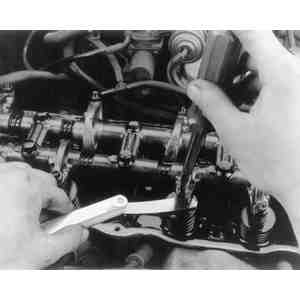
| Fig. 2: Use a flat feeler gauge to check clearance
between each valve and valve rocker lever. Turn the adjusting screw
to attain the appropriate setting
|
| Fig. 3: After the proper setting is attained, hold
the adjusting screw stationary while tightening the locknut

|
- Refer to the valve clearance columns of the Tune-Up Specifications chart
found in this section. Insert a flat feeler gauge of the proper dimension
between the exhaust valve and the exhaust valve rocker lever for the No. 1
cylinder. (The exhaust valve is in line with the front exhaust manifold passage.)
The gauge should slide between these two parts with a slight pull. If the
gauge will not slide readily, or there is no resistance when pulling it through,
loosen the locknut and use a screwdriver to rotate the adjusting screw clockwise
to tighten the adjustment, or counterclockwise to loosen it. When a slight
pull is obtained, hold the adjusting screw in place with a screwdriver and
use a box or open end wrench to tighten the locknut. If the adjustment has
tightened up, change the setting of the adjusting screw. If a great deal of
effort is required to pull the gauge (adjustment too tight), burned valves
may result.
- Select the gauge for the adjusting dimension of the intake valves (see the
Tune-Up Specifications chart). Repeat Step 3 for the front intake valve (lined
up with the front intake manifold passage).
- Adjust the remaining valves shown in the illustration (No. 2 Intake and
No. 3 Exhaust). Then, rotate the engine exactly one full revolution, so that
the timing marks for Top Dead Center (TDC) are again lined up. Finally, adjust
the remaining valves (No. 3 and No. 4 intake and No. 2 and No. 4 exhaust).
Make sure you use the proper thickness gauge on each side.

