- Check the top deck of the block for distortion by running a straightedge
along both sides, both ends, and diagonally. Check for distortion exceeding
0.006 in. (0.15mm), by attempting to insert an appropriate size flat feeler
gauge between the block deck and the lower edge of the straightedge all along
its length, in every direction shown. If distortion exceeds the limit, have
the block top deck ground by a competent machine shop or, if distortion is
excessive, replace the block.
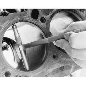
| Fig. 1: A telescoping gauge or inside micrometer
may be used to measure the cylinder diameter bore
|
| Fig. 2: Measure the diameter of each cylinder at
three different depths; also, take three additional readings, perpendicular
to the first ones
|
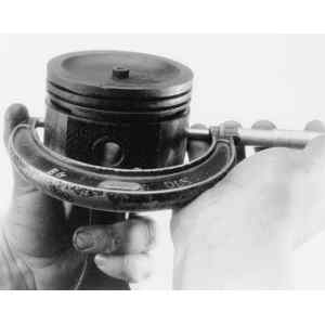
| Fig. 3: Measure the piston's outside diameter using
a micrometer
|
- Also inspect the block for cracks or wetness, indicating coolant has leaked
through the cracks. If you have any doubt about such problems, you should
have the block inspected by the Zyglo® , Magnaflux® or
similar process, to ensure it can be reused without risk of leakage. Pressure
testing is another means by which the block may be tested for cracks.
NOTE: The Zyglo® process coats parts with a fluorescent
dye penetrant that is suitable for any material. Magnaflux® is
a magnetic process applicable only to ferrous materials.
- Measure the diameter of each cylinder at the six locations shown. Subtract
the minimum dimension from the maximum dimension. If this difference exceeds
0.0059 in. (0.15mm), or the difference between cylinders exceeds 0.0007 in.
(0.01778mm), cylinders must be bored and oversize pistons installed. If boring
is required, you should base the amount that you remove on the dimensions
of an oversize piston. When one cylinder is bored, all other cylinders must
be bored the same amount. Any time this type of machining is done, it should
be documented. Wall scoring or signs of piston seizure also mean cylinders
must be rebored.
NOTE: Even if only one cylinder is damaged, all must be
bored and the same oversize pistons installed (for balance). Pistons are
offered in oversizes of 0.010 in. (0.254mm) and 0.020 in. (0.508mm) for
most engines.
| Fig. 4: Measure piston diameter at the position shown
|
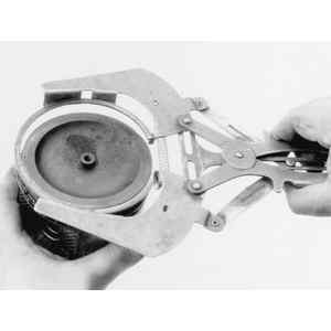
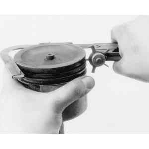
| Fig. 5: Use a ring expander tool to remove the piston
rings
|
| Fig. 6: Clean the piston grooves using a ring groove
cleaner . . .
|
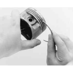
| Fig. 7: . . . or part of a broken piston ring. Be
careful, since the ring is sharp
|
- On 2.0L (Code FE), 2.2L and 3.0L engines, test the oscillation torque of
the rod by holding the piston in a horizontal position, and raising the rod
until it touches the piston skirt, then releasing it. The rod should descend
freely; otherwise, replace the piston and/or piston pin. If replacement is
indicated, press the piston pin out with tools designed for this purpose.
NOTE: This procedure requires the use of a hydraulic press
that produces and measures total pressures of 1,100–3,300 lbs. (500–1,500
kg). You may wish to remove the piston/rod assemblies yourself and have
the pressing operations performed at a competent automotive machine shop.
- On gasoline engines, other than the 1.3L engine, if the pressure required
to press the pin from the piston is less than 1,100 lbs. (500 kg), replace
the piston pin or the connecting rod.
- Measure piston diameter in the thrust direction, below the bottom of the
oil ring groove and 90 degrees from the piston pin, as shown in the illustration.
This dimension must compare with cylinder diameter so as to produce piston-to-cylinder
clearance that is within specifications. If clearance exceeds the maximum
wear specification, all cylinders must be bored and appropriate oversize pistons
must be installed. If the clearance is within specification, only light finish
honing is required.
- Using a ring expander tool, as illustrated, remove the piston rings. The
various rings on each piston are not identical. Be careful not to mix them
up, in case they may be reused.
NOTE: If the piston is to be replaced, also install new
piston rings.
- Clean the pistons thoroughly with a suitable solvent or in a dip tank. All
the ring lands must be free and clear of any carbon deposits. Use a ring groove
cleaning tool or a broken piston ring, which allows you to reach the innermost
part of the land. DO NOT use a file or wire brush to clean the piston. Inspect
the rings for damage or cracks and measure side clearance, as shown, using
a new piston ring. Also measure end-gap, as shown, with the
rings near the bottom of the cylinder — below the area of
ring wear. This should be done even for new rings.
- Install the connecting rods in a jig designed to test straightness and check
that the bend or twist does not exceed 0.0016 in. (0.04mm) per 3.94 in. (100mm)
of length on all 1978–88 gasoline engines. On 1989 1.6L engines, the
bend or twist should not exceed 0.0078 in. (0.20mm) per 3.94 in. (100mm),
and on 1989 2.2L and 3.0L engines, the limit is 0.0024 in. (0.06mm).
- Measure the piston pin diameter and the piston pin hole diameter each in
eight places, as illustrated. Compare the readings and replace any out-of-round
components. Also, if pin-to-hole clearance is beyond the specified limit,
replace the piston and/or piston pin.
| Fig. 8: Check the piston ring side clearance using
a new ring and a feeler gauge
|
| Fig. 9: Measure ring end-gap by placing the ring
inside the cylinder, in the area of ring-induced wear. Use an inverted
piston to keep the ring from cocking
|
| Fig. 10: Use an inside caliper to measure the piston
pin hole diameter in eight places
|
| Fig. 11: Use a micrometer to take eight measurements
of a piston pin
|

