NOTE: Be sure that the cylinder head is cold before removal,
as this will help prevent warpage.
- Disconnect the negative battery cable.
- Rotate the crankshaft so that the No. 1 cylinder is at TDC.
- Drain the cooling system.
- Remove the air cleaner assembly.
- On rear wheel drive models, remove the water pump.
- Remove the distributor, as described earlier in this section.
- Disconnect the front catalytic converter from the exhaust manifold, then
unfasten and remove the exhaust manifold from the cylinder head.
- Disconnect all applicable electrical wires and leads.
- If necessary, remove the alternator drive belt, alternator and adjusting
strap.
- Remove the thermostat housing and thermostat.
| Fig. 1: Removing the tensioner — GLC
front wheel drive models
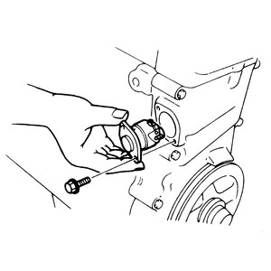
|
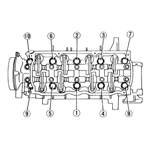
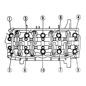
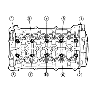
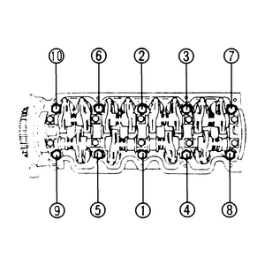
| Fig. 2: Cylinder head bolt loosening sequence for
GLC and 1979–82 626 (1981–85 GLC shown)
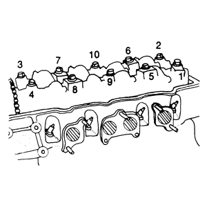
|
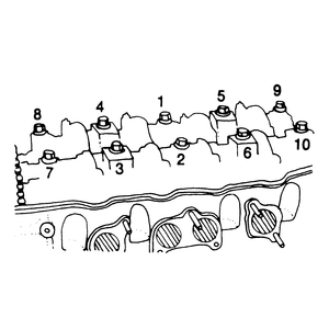
| Fig. 3: Cylinder head bolt tightening sequence for
GLC and 1979–82 626 (1981–85 GLC shown)
|
- Disconnect the accelerator linkage.
- Remove the intake manifold and carburetor assembly.
- Remove the rocker arm cover and gasket, along with the semi-circular oil
seal(s). Clean the mating surface of the rocker arm cover.
- On front wheel drive GLC models, remove the tensioner (chain adjuster) from
the timing chain cover.
- Remove the locknut, washer and, on the 626 and GLC wagon only, the distributor
drive gear and spacer from the camshaft.
- If so equipped, remove the cylinder head-to-cylinder block bolt.
NOTE: Although 1.3L and 1.4L engines have their camshaft
sprocket at the opposite end, they utilize the same loosening sequence (in
reference to the front of the vehicle).
- Loosen the cylinder head bolts in several stages of the illustrated sequence.
(In order to avoid cylinder head distortion, only loosen the bolts a few turns
at a time.)
NOTE: The cylinder head bolts also retain the rocker arm
assembly and camshaft.
- Remove the rocker arm assembly.
- Separate the camshaft sprocket and chain from the camshaft. Be sure to support
the timing chain so the tensioner will not come apart. On the front wheel
drive GLC, even though the tensioner has been removed, you still must support
the camshaft sprocket so the timing relationship between the chain links and
upper/lower sprockets will not be lost.
NOTE: Do not remove the camshaft sprocket from the chain.
Maintain the relationship between the timing chain and sprocket by temporarily
wiring them together.
- Remove the camshaft.
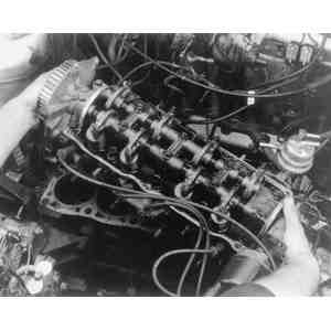
- Lift off the cylinder head and remove the gasket. Thoroughly clean off all
old gasket material from the mating surfaces and inspect the components for
wear or damage, as described later in this section. Repair or replace parts,
as necessary.
To install:
- Install a new head gasket on the engine block with all oil passages, water
passages, and bolt holes matching up.
- Place the cylinder head into position, aligning the dowels.
- Coat all the camshaft bearing surfaces with clean engine oil before installing
the camshaft. (These include the cylinder head and cap or bearing insert inner
surfaces, as well as the camshaft journal surfaces).
- Slide the sprocket (with the timing chain still attached) onto the camshaft.
Install the camshaft and rocker arm assembly.
NOTE: The rocker arm assembly must be properly positioned
before tightening the cylinder head bolts.
- Slide the rocker arm assembly to one side until the adjusting studs are
offset 0.04 in. (1mm) from the centers of the valve stems. (This is necessary
for proper valve rotation.) Then, torque the bolts using several stages of
the indicated sequence.
NOTE: Although 1.3L and 1.4L engines have their camshaft
sprocket at the opposite end, they utilize the same tightening sequence
(in reference to the front of the vehicle).
- Check the valve clearance using a feeler gauge and adjust, if necessary,
as described in Section 2.
- If applicable, install the cylinder head-to-cylinder block bolt.
- On the 626 and GLC wagon, align the key groove with the pin, then install
the spacer and distributor drive gear on the camshaft.
- Install the washer and sprocket locknut on the camshaft. Tighten the locknut
to 51–58 ft. lbs. (70–80 Nm).
- Check the camshaft end-play (clearance between the sprocket and thrust plate)
with a feeler gauge. If the clearance exceeds 0.008 in. (0.20mm), replace
the thrust plate.
- On front wheel drive GLC models, reset the chain adjuster by pushing the
sleeve completely into the body, then securing it with the built-in latch
and pin. Install this device on the timing chain cover.
NOTE: After the adjuster is installed, the pin is automatically
released by the timing chain when the engine is cranked.
- Apply RTV or rubber sealer to the semi-circular oil seal(s) and install
on the cylinder head with the "OUT'' mark facing away from the engine.
- Position a new gasket on the cylinder head, then install the rocker arm
cover. Tighten the retaining nuts to 1.1–1.4 ft. lbs. (1.5–1.9
Nm), or the bolts to 1.4–2.5 ft. lbs. (1.9–3.4 Nm).
- Complete the installation of the remaining components in reverse of the
removal procedure. Be sure to use new gaskets and O-rings, and to properly
tension the drive belt, if necessary.
- Refill the cooling system to the proper level and connect the negative battery
cable. Start the engine and check for leaks.
NOTE: Be sure that the cylinder head is cold before removal,
as this will help prevent warpage.
- Rotate the crankshaft so that the No. 1 cylinder is at TDC.
- Drain the cooling system.
- Remove the air cleaner assembly.
- Remove the distributor, as described earlier in this section.
- Remove the thermostat housing and thermostat.
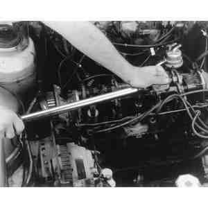
| Fig. 4: With the bolts removed, use a prytool to
carefully separate the cylinder head from the engine block
|
| Fig. 5: Lift the cylinder head from the engine block
|
| Fig. 6: Remove the cylinder head gasket from the
engine block

|
| Fig. 7: Cylinder head bolt loosening sequence — 1983–87
626
|
| Fig. 8: Cylinder head bolt tightening sequence — 1983–87
626
|
| Fig. 9: Torque the cylinder head bolts in several
stages, beginning with the front center bolt
|
| Fig. 10: Apply sealant to the shaded areas (indicated
by the arrows) before installing the rocker arm cover — 1983–87
626
|
- Remove the fuel pump.
- Disconnect the accelerator cable.
- Remove the intake manifold and carburetor assembly.
- On vehicles equipped with air conditioning, remove the alternator and alternator
strap.
- On vehicles equipped with air conditioning, remove the A/C compressor and
alternator bracket installation bolts.
- Disconnect the engine ground wire.
- Remove the upper timing belt cover.
- Remove the timing belt, as described later in this section.
- Disconnect the secondary air pipes.
- Unfasten the oxygen sensor connector.
- Remove the exhaust manifold insulator assembly.
- Remove the three nuts and gasket which retain the front catalytic converter
to the exhaust manifold.
- Remove the cylinder head's rear housing and gasket.
- Remove the rocker arm cover and gasket.
- Remove the cylinder head bolts and washers in the appropriate sequence,
as illustrated.
NOTE: In order to avoid cylinder head distortion, loosen
and remove the cylinder head bolts only a few turns at a time.
- Remove the cylinder head and exhaust manifold as an assembly. If necessary,
first unfasten and remove the exhaust manifold from the cylinder head.
NOTE: Exhaust manifold removal is normally unnecessary
in order to remove the cylinder head.
- Remove the cylinder head gasket. Thoroughly clean off all old gasket material
from the mating surfaces and inspect the components for wear or damage, as
described later in this section. Repair or replace parts, as necessary.
To install:
- If applicable, re-attach the exhaust manifold to the cylinder head, using
a new gasket. (If preferred, this step may be performed after the cylinder
head is installed.)
- Install a new head gasket on the engine block with all oil passages, water
passages, and bolt holes matching up.
- Place the cylinder head into position, then insert the cylinder head washers
and bolts. Torque the bolts to 59–65 ft. lbs. (82–88 Nm) in several
stages, following the proper sequence.
- Position a new gasket on the rocker arm cover. Apply a coating of sealant
to the portions of the rocker shaft assembly which are shaded in the illustration,
then position the gasket and cover on the cylinder head. Insert the retaining
bolts with their seal washers and tighten to 2.2–2.9 ft. lbs. (3–4
Nm).
- Complete the installation of the remaining components in reverse of the
removal procedure. Be sure to use new gaskets and O-rings, and to properly
tension the drive belt(s). For information on timing belt installation and
adjustment, refer to the procedure later in this section.
- Refill the cooling system to the proper level. Start the engine and check
for leaks.
- Disconnect all applicable electrical wires and leads.
- Disconnect the drive belt(s), then remove the alternator.
- Remove the cylinder head's rear housing and gasket.
NOTE: Be sure that the cylinder head is cold before removal,
as this will help prevent warpage.
- Disconnect the negative battery cable.
- Drain the cooling system.
- Disconnect the accelerator cable.
- On turbocharged models, disconnect the secondary air pipe from the exhaust
manifold.
- Remove the distributor.
- Remove the rear housing and gasket.
- Disconnect the intake air hose.
- On turbo models, disconnect the secondary air pipes from the front catalytic
converter. Then, disconnect the oil pipe from the turbocharger.
- Remove the exhaust manifold insulator. On turbo models, also remove the
two smaller insulators near the front catalytic converter.
- On turbo models, remove the bracket connecting the turbocharger to the front
catalytic converter. Disconnect the front catalytic converter and the oil
return hose from the turbocharger. Then, disconnect the water inlet and outlet
hoses, and the EGR pipe.
- On non-turbo models, disconnect the exhaust pipe from the manifold.
- Remove the exhaust manifold (or manifold/turbocharger assembly) and gasket.
- Remove the intake manifold assembly and gasket.
- Remove the upper timing belt cover.
- Remove the timing belt, as described later in this section.
- Remove the rocker arm cover.
- In order to avoid cylinder head distortion, loosen and remove the cylinder
head bolts only a few turns at a time. The bolts should be removed in the
appropriate sequence, as illustrated.
- Lift off the cylinder head and remove the gasket. Thoroughly clean off all
old gasket material from the mating surfaces and inspect the components for
wear or damage, as described later in this section. Repair or replace parts,
as necessary.
To install:
- Install a new head gasket on the engine block with all oil passages, water
passages, and bolt holes matching up.
- Place the cylinder head into position, then insert the cylinder head washers
and bolts. Torque the bolts to 59–65 ft. lbs. (82–88 Nm) in several
stages, following the proper sequence.
- Position a new gasket on the rocker arm cover. Apply a coating of sealant
to the portions of the rocker shaft assembly which are shaded in the illustration,
then position the gasket and cover on the cylinder head. Insert the retaining
bolts with their seal washers and tighten to 2.2–2.9 ft. lbs. (3–4
Nm).
- Complete the installation of the remaining components in reverse of the
removal procedure. Be sure to use new gaskets and O-rings, and to properly
tension the drive belt(s). For information on timing belt installation and
adjustment, refer to the procedure later in this section.
- Refill the cooling system to the proper level. Start the engine and check
for leaks.
- Disconnect the negative battery cable and drain the cooling system.
- Remove or disconnect the following parts:
- Air cleaner
- Oil dipstick
- Accelerator cable and (if so equipped) cruise control cable
- Fuel hoses (drain fuel into a suitable container, then plug them)
- Fuel pump (carbureted engines only)
- Heater hoses
- Power brake vacuum hose
- Emissions canister hoses
- Engine electrical harness connectors
- High tension wires (label them first)
- Distributor
- Spark plugs
- Secondary air pipe assembly (carbureted engines only)
- Front engine hanger and the nearby ground wire
- Upper radiator hose (at the thermostat housing)
- Water bypass hose and bracket
- Intake and exhaust manifolds
- Engine side cover
- Alternator and drive belt(s)
- Water pump pulley
- Crankshaft pulley and baffle plate
- Remove the timing belt covers, as described later in this section. Rotate
the crankshaft until the matchmarks on the camshaft and timing belt pulleys
are aligned with the corresponding marks on the cylinder block. Then, remove
the timing belt, also as described later in this section.
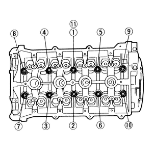
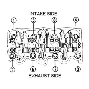
| Fig. 11: Cylinder head bolt loosening sequence — 1986–87
323 non-turbo
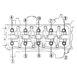
|
| Fig. 12: Cylinder head bolt loosening sequence — 1988–89
323 non-turbo
|
| Fig. 13: Cylinder head bolt torque sequence — 1986–87
323 non-turbo

|
| Fig. 14: Cylinder head bolt torque sequence — 1988–89
323 non-turbo
|
- If you will be removing the camshaft or performing other major work on the
cylinder head itself, remove the camshaft pulley. To remove the pulley, insert
a small prytool in one of the slots on the face of the pulley to hold it in
place while loosening the bolt with a wrench. After removing the bolt, withdraw
the pulley from the camshaft.
- If you will be removing the camshaft or performing other major work on the
cylinder head itself, also remove the rocker assembly, as described earlier
in this section.
- Remove the rear engine hanger from the cylinder head.
- Loosen the cylinder head cover retaining bolts and remove the cover.
- Loosen the cylinder head bolts using several stages of the sequence shown.
Remove the head bolts, then lift off the cylinder head and head gasket. If
necessary, remove the thermostat cover and thermostat.
- Thoroughly clean both mating surfaces and inspect the components for warping
or other damage, as described later in this section. Repair or replace parts,
as necessary.
To install:
- If removed, install the thermostat with the jiggle pin facing upward and
the printed side of the new gasket facing the thermostat. Torque the cover
bolts to 14–19 ft. lbs. (19–26 Nm).
- Install a new head gasket on the engine block with all oil passages, water
passages, and bolt holes matching up.
- Place the cylinder head into position and install the head bolts finger-tight.
Then, torque the cylinder head bolts to 63–67 ft. lbs. (85–91
Nm) in three stages, using the appropriate sequence.
NOTE: Step 11 of the torque sequence only applies to 1988
engines.
- Install the camshaft pulley onto the end of the camshaft with the dowel
pin and keyway in proper positions and the matchmark straight up. Install
the retaining bolt and torque it to 36–45 ft. lbs. (49–61 Nm).
- Perform the remaining installation steps in reverse of the removal procedure.
Note the following points:
- Replace all gaskets which were removed with new ones.
- Install and adjust the timing belt, as described later in this section.
- If applicable, install the rocker assembly following the torque sequence
and specifications outlined earlier in this section.
- Torque the intake and exhaust manifold bolts/nuts to specification.
- When installing the distributor, be sure that the distributor rotor
is pointing in the direction of the No. 1 cylinder wire connection at
the cap. The distributor's drive blade should then be aligned with the
oil hole on the base of the distributor prior to engaging the distributor
drive gear with the corresponding gear on the camshaft.
- Adjust the valves as described in Section 2.
- Apply a coating of sealer along the groove in the cylinder head cover
before installing the gasket, and torque the bolts to 43–78 inch
lbs. (5–9 Nm).
- Refill the cooling system and connect the negative battery cable.
- Start the engine and check for leaks.
- Properly relieve the fuel system pressure. Disconnect the negative battery
cable. Drain the cooling system.
- Remove the air cleaner assembly.
- Remove the distributor, distributor wires and spark plugs.
- Remove the air intake pipe, air pipe, air bypass valve and hoses.
- Remove the radiator.
- Remove the engine side cover and the engine under cover.
- Disconnect the exhaust pipe at the exhaust manifold. Remove the turbocharger
mounting bracket, along with the exhaust manifold and turbocharger insulators.
Unfasten the exhaust manifold retaining bolts, then remove the exhaust manifold
and turbocharger assembly from the engine.
- Remove the radiator hose and coolant bypass pipe. Disconnect the accelerator
cable.
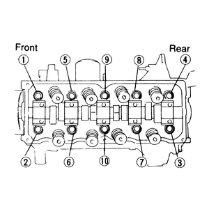
| Fig. 15: Cylinder head bolt loosening sequence — 323
turbo
|
| Fig. 16: Cylinder head bolt torque sequence — 323
turbo
|
- Disconnect all required electrical connections, vacuum hoses and fuel line
couplings.
- Remove the surge tank and bracket.
- Loosen the cylinder head cover retaining bolts and remove the cover.
- Remove the timing cover assembly retaining bolts. Remove the timing cover
assembly.
- Remove the timing belt, as described later in this section.
- Loosen the cylinder head bolts gradually in the appropriate sequence. Remove
the cylinder head and intake manifold assembly from the engine.
- Remove the attaching bolts and separate the intake manifold from the cylinder
head. If necessary, remove the thermostat cover and thermostat. Remove any
old gasket material and clean all gasket mounting surfaces.
- Thoroughly clean the cylinder head and engine block mating surfaces, then
inspect the components for warping or other damage, as described later in
this section. Repair or replace parts, as necessary.
To install:
- If removed, install the thermostat with the jiggle pin facing upward and
the printed side of the new gasket facing the thermostat. Torque the cover
bolts to 14–19 ft. lbs. (19–26 Nm).
- Install the intake manifold with a new gasket. Torque the intake manifold
bolts to 14–19 ft. lbs. (19–26 Nm).
- Place a new head gasket onto the engine block and position the cylinder
head. Install the bolts and torque them to 56–60 ft. lbs. (76–81
Nm) in several stages, following the proper sequence.
NOTE: Step 11 of the torque sequence only applies to 1988
engines.
- Apply sealant to the cylinder head cover and install a new gasket. Torque
the cover bolts to 26–35 inch lbs. (3–4 Nm).
- Complete the installation of the remaining components in reverse of the
removal procedure.
- Refill the cooling system to the proper level and connect the negative battery
cable.
- Start the engine and check for leaks. Perform any necessary tune-up adjustments.
- Disconnect the negative battery cable and drain the cooling system.
- Disconnect the spark plug wires and remove the spark plugs.
- Disconnect the accelerator cable. If equipped with an automatic transaxle,
disconnect the throttle cable and route it off to the side.
- Remove the air intake pipe.
- Remove the air intake pipe and fuel hose. Cover the fuel hose to prevent
leakage.
- Remove the upper radiator hose, water bypass hose, heater hose, oil cooler
hose (turbo only) and brake vacuum hose.
- Remove the 3-way and EGR solenoid valve assemblies.
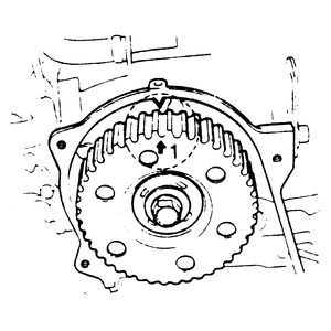
| Fig. 17: Camshaft pulley and front housing alignment
marks — 1988–89 626 and MX-6
|
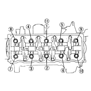
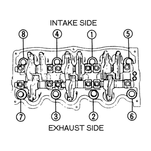
| Fig. 18: Cylinder head bolt loosening sequence — 1988–89
626 and MX-6
|
| Fig. 19: Cylinder head bolt torque sequence — 1988–89
626 and MX-6
|
- Disconnect the engine harness connector and ground wire.
- Remove the vacuum chamber and exhaust manifold insulator.
- Remove the EGR pipe, turbo oil pipes (if so equipped) and exhaust pipe.
- Remove the exhaust manifold and the turbocharger, if so equipped.
- Remove the intake manifold bracket and the intake manifold.
- Remove the distributor, as described earlier in this section.
- Loosen the air conditioning compressor and bracket assembly; position and
tie it off to the side and out of the way.
NOTE: Do not disconnect the refrigerant lines.
- Remove the upper timing belt cover and the timing belt tensioner spring.
- To remove the timing belt, perform the following:
- Rotate the crankshaft so that the 1 on the camshaft
pulley is aligned with the timing mark on the front housing (see illustration).
- When the timing marks are aligned, loosen the timing belt tensioner
lockbolt. Pull the tensioner as far out as it will go, then temporarily
tighten the lockbolt to hold it there.
- Lift the timing belt from the camshaft pulley and position it out of
the way.
- Loosen the retaining bolts, then remove the cylinder head cover and gasket.
- Loosen the cylinder head bolts in the proper sequence, then remove the cylinder
head and head gasket.
- Thoroughly clean the cylinder head and engine block mating surfaces, then
inspect the components for warping or other damage as described later in this
section. Repair or replace parts as necessary.
To install:
- Position a new head gasket on the mating surface of the engine block.
NOTE: Turbocharged and non-turbocharged engines use different
cylinder head gaskets. To ensure proper sealing and compression, make sure
that the proper type gasket is being installed.
- Position the cylinder head on the gasket.
- Coat the cylinder head bolt threads and seat faces with clean engine oil,
then torque the bolts to 59–64 ft. lbs. (80–87 Nm) in three stages,
following the proper sequence.
- Apply a suitable sealant to the 4 corners where the rocker assembly end
caps meet the cylinder head, then install the cylinder head cover with a new
gasket. Torque the cover bolts to 52–69 inch lbs. (6–8 Nm).
- Make sure that the camshaft pulley and front housing timing marks are still
aligned, then install the timing belt, as described later in this section.
- Complete the remainder of the installation procedures in reverse of their
removal. Be sure to replace all gaskets which were removed with new ones.
- Refill the cooling system to the proper level and connect the negative battery
cable.
- Start the engine and check for leaks. Check and adjust the ignition timing
and idle speed, as described in Section 2.
NOTE: The following procedure applies to removal of either
side cylinder head.
- Properly relieve the fuel system pressure. Disconnect the negative battery
cable.
- Drain the coolant and remove the air cleaner assembly.
- Rotate the crankshaft so that the No. 1 cylinder is at TDC. (All the pulley
matchmarks should be aligned.)
- Remove the timing cover assembly. Mark the timing belt's direction of rotation
(if it will be re-used), then remove the belt.
- Disconnect and plug the canister, brake vacuum and fuel hoses. If equipped
with an automatic transmission, disconnect the automatic transmission vacuum
hose.
- Remove the 3-way solenoid valve assembly and disconnect all engine harness
connectors and grounds.
- If equipped with an automatic transmission, remove the dipstick. Disconnect
the required vacuum hoses. Disconnect the accelerator linkage.
- Remove the distributor, as described earlier in this section, and the EGR
pipe.
- Remove the six extension manifolds. Remove and discard the O-rings from
the extension manifolds (new ones must be used). Remove the intake manifold
by loosening the retaining bolts in the proper sequence.
- Remove the cylinder head cover, gasket and seal washers.
- Remove the insulator and center exhaust pipe. Disconnect the exhaust manifold
retaining bolts. Remove the exhaust manifold with insulator.
- Remove the seal plate.
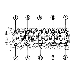
| Fig. 20: Cylinder head bolt loosening sequence — 929
|
| Fig. 21: Measure the length of each head bolt before
installation, and replace any that do not meet specifications — 929

|
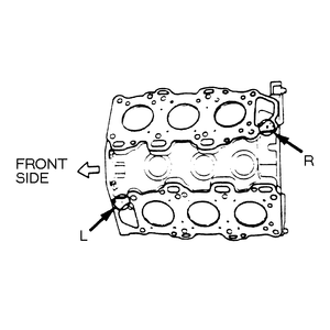
| Fig. 22: Be sure to properly position the cylinder
head gaskets with the marks facing up — 929
|
| Fig. 23: Cylinder head bolt torque sequence — 929
|
- Remove the cylinder head retaining bolts in the proper sequence, in 2 or
3 stages. Remove the cylinder head from the vehicle.
- Thoroughly clean the cylinder head and engine block mating surfaces, then
inspect the components for warping or other damage, as described later in
this section. Repair or replace parts, as necessary.
To install:
- After they have been cleaned, measure the length of each cylinder head bolt.
Replace any out-of-specifications bolts as required.
Length:
- Intake — 4.25–4.29 in. (108–109mm)
- Exhaust — 5.43–5.47 in. (138–139mm)
- Check the oil control plug projection at the cylinder block. The projection
should be 0.0209–0.0224 in. (0.53–0.57mm). If correct, apply clean
engine oil to a new O-ring and position it on the control plug.
- Position the new correct side cylinder head gasket on the engine block.
NOTE: A left bank gasket should be positioned with the L mark
facing up, and a right bank gasket should be positioned with the R mark
facing up.
- Install the cylinder head onto the block. Tighten the head bolts in the
following manner:
- Coat the threads and the seating faces of the head bolts with clean
engine oil.
- Torque the bolts in the proper sequence to 14 ft. lbs. (19 Nm).
- Paint a mark on the head of each bolt.
- Using this mark as a reference, tighten the bolts in the proper sequence
an additional 90 degrees.
- Repeat Step d.
- Complete the installation of the remaining components in reverse of their
removal. Be sure to replace all gaskets which were removed with new ones.
For timing belt installation and adjustment, refer to the procedure later
in this section.
- Refill the cooling system to the proper level and connect the negative battery
cable.
- Start the engine and check for leaks. Perform any required tune-up adjustments.

