

- Check the housing for signs of gas or water leakage.
- Remove the sealing compound from the housing surface with a cloth or brush
soaked in solvent or thinner.
- Remove the carbon deposits from the front housing with extra fine emery
cloth. When using a carbon scraper, take extra care not to damage the surface
of the housing.
- Check for distortion by placing a straightedge on the surface of the housing.
Measure the clearance between the straightedge and the housing with a feeler
gauge. If the clearance is greater than 0.0016 in. (0.04mm) at any point,
replace the housing.
| Fig. 1: Check the rotor housings for warpage along
these lines
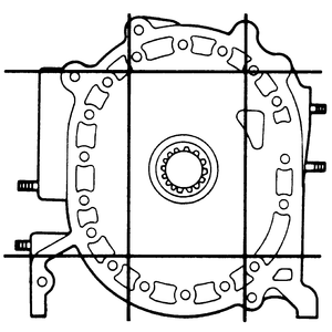
|
| Fig. 2: Measuring stepped wear at the sides of the
housing
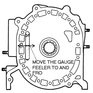
|
| Fig. 3: Measuring stepped wear across the middle
of the housing
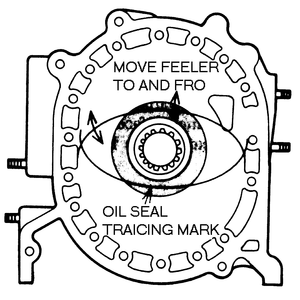
|
| Fig. 4: Measuring stepped wear caused by the oil
seal

|
- Use a dial indicator with a sled attachment (gauge body) to check for wear
on the rotor contact surfaces of the housing. Mazda offers such an attachment
under part number 49–0727–570 or equivalent. To check for stepped
wear on the rotor housing sliding surfaces, mount the dial indicator on the
sliding surface of the housing. To measure stepped wear caused by the side
seal at the sides of the housing, move the dial indicator gauge feeler to
and fro as shown in the illustration. The wear limit is 0.0039 in. (0.10mm).
Check the side seal stepped wear across the middle of the housing with the
dial indicator, moving it as shown in the illustration. The wear limit inside
the oil seal tracing marks is 0.0004 in. (0.01mm), and the wear limit outside
the oil seal tracing marks is 0.0039 in. (0.10mm). Check for stepped wear
by the oil seal with the dial gauge. The wear limit is 0.0008 in. (0.02mm).
- If the front, intermediate and/or rear side housings are beyond the above
wear limits, they can be ground if the required finish can be maintained.
If the wear is greater than the values provided above, replace the housing.
NOTE: The wear at either end of the minor axis is greater
than at any other point on the housing. However, this is normal and should
not be cause for concern.
- Examine the teeth of the stationary gear for wear or damage.
- Be sure that the main bearing shows no signs of excessive wear, scoring,
or flaking.
- Check the main bearing-to-eccentric journal clearance by measuring the journal
with a vernier caliper and the bearing with a pair of inside calipers. The
standard clearance is 0.0016–0.0031 in. (0.04–0.08mm). If the
clearance exceeds the limit, replace the front main bearing as described later
in this section.
- Unfasten the securing bolts, if used. Remove the stationary gear and main
bearing assembly from the housing, using puller tool 49–0813–235
or equivalent.
- Press the main bearing out of the stationary gear.
- Press a new main bearing into the stationary gear, so that it is in the
same position as the old one.
- Align the slot in the stationary gear flange with the dowel pin in the housing,
then press the gear into place. On later engines, align the bearing lug with
the slot in the gear. Install the securing bolts, if applicable.
Inspect the rear stationary gear and main bearing in a similar manner to the
front. In addition, examine the O-ring, which is located in the stationary gear,
for signs of wear or damage. Replace the O-ring, if necessary. If the stationary
gear must be replaced, follow the rear main bearing replacement procedure.
- Remove the rear stationary gear securing bolts.
- Drive the stationary gear out of the rear housing with a brass drift.
- Apply a light coating of grease to a new O-ring and fit it into the groove
on the stationary gear.
- Apply sealer to the flange of the stationary gear.
- Install the stationary gear on the housing so that the slot on its flange
aligns with the pin on the rear housing. On later engines, align the bearing
lug with the housing slot. Use care not to damage the O-ring during installation.
- Tighten the stationary gear bolts evenly, in several stages, to 12–17
ft. lbs. (16–23 Nm).
- Examine the inner margin of both housings for signs of gas or water leakage.
- Wipe the inner surface of each housing with a clean cloth to remove the
carbon deposits.
- Clean all of the rust deposits out of the cooling passages of each rotor
housing.
- Remove the old sealer using the proper removal solvent.
- Examine the chromium-plated inner surfaces for scoring, flaking, or other
signs of damage. If any are present, the housing must be replaced.
- Check the rotor housings for distortion by placing a straightedge on the
axes.
- If distortion exceeds 0.002 in. (0.05mm), replace the rotor housing.
- Check the widths of both rotor housings, at points A, B, C, and D near the
trochoid surfaces of each housing, using a vernier caliper, as illustrated.
Compare the difference between the value obtained at point A and the minimum
value of points B, C and D. If the difference between the values obtained
is greater than 0.0024 in. (0.06mm), replace the housing. A rotor housing
in this condition will be prone to gas and coolant leakage.
- Check the rotor for signs of blow-by around the side and corner seal areas.
- The color of the carbon deposits on the rotor should be brown, just as in
a piston engine. Usually, the carbon deposits on the leading side of the rotor
are brown, while those on the trailing side tend toward black (as viewed from
the direction of rotation).
- Remove the carbon on the rotor with a scraper or extra fine emery paper.
Use the scraper carefully when cleaning the seal grooves to avoid any damage.
- Wash the rotor in solvent and blow it dry with compressed air.
- Examine the internal gear for cracks or damaged teeth. If the internal gear
is damaged, the rotor and gear must be replaced as a single assembly.
- With the oil seal removed, check the land protrusions by placing a straightedge
over the lands. Measure the gap between the rotor surface and the straightedge
with a feeler gauge.
- Check the clearance between the housings and the rotor on both of its sides:
- Measure the rotor width with a vernier caliper at the points indicated
in the corresponding illustration.
- Compare the rotor width against the width of the previously measured
rotor housing.
- Replace the rotor, if the difference between the two measurements is
not 0.0047–0.0074 in. (0.12–0.19mm) for the 1979–85
carbureted engine or 0.0047–0.0083 in. (0.12–0.21mm) for the
1984–90 fuel injected engine.
- If the clearance exceeds the specified values, replace
the rotor. If the clearance is less than specification, it
means that the internal gear must be removed. To dislodge the gear from the
rotor bore, smack it lightly with a plastic-faced hammer, being careful not
to damage the rotor. With the gear removed, recheck the side housing-to-rotor
clearance again.
- The corner seal bores can be checked with a gauge (tool number 49 0839 15
or equivalent), available from Mazda. If neither end of the gauge can be fit
into the bores, it is safe to reuse the original corner seals. If the "go''
side of the gauge does fit into the bore, but the larger "no go'' side does
not, use new seals. If both sides of the gauge fit into the bores, the rotor
must be replaced.
- Check the rotor bearing for wear, flaking, scoring or damage. Replace the
bearing if these conditions are found. Check the bearing oil clearance by
measuring the appropriate bearing journal diameter on the eccentric shaft
with a micrometer. Next, measure the inner diameter of the rotor bearing.
NOTE: The standard rotor bearing journal diameter is 2.913
in. (74mm).
- Find the oil clearance by subtracting the rotor bearing diameter from the
rotor journal diameter. The standard clearance is 0.0016-0.0031 in. (0.04-0.08mm).
If the clearance is greater than 0.0039 in. (0.10mm), replace the rotor bearing
as described later in this section.
- Check the clearance between the rotor bearing and the rotor journal on the
eccentric shaft. Measure the inner diameter of the rotor bearing and the outer
diameter of the journal. The wear limit is 0.0039 in. (0.1mm); replace the
bearing if it exceeds specification.
- Place the rotor on the support so that the internal gear is facing downward.
Using puller tool 49–0813–240 (or equivalent) without its adapter
ring, press the bearing out of the rotor. Being careful not to damage the
internal gear.
- Place the rotor on the support with the internal gear facing upward. Place
the new rotor bearing on the rotor so that the bearing lug is in line with
the slot of the rotor bore.
- Remove the screws which attach the adapter ring to the special tool. Using
the special tool and adapter ring, press fit the new bearing until the bearing
is flush with the rotor boss.
- Examine the oil seal while it is mounted in the rotor.
- If the width of the oil seal lip is greater than 0.020 in. (0.5mm), replace
the oil seal.
- If the protrusion of the oil seal is greater than 0.020 in. (0.5mm), replace
the seal.
| Fig. 5: Oil seal width and protrusion
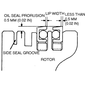
|
- Pry the seal out by inserting a small prybar into the slots on the rotor.
Be careful not to deform the lip of the oil seal if it is to be reinstalled.
- Fit both the oil seal springs into their respective grooves, so that their
ends are facing upward and their gaps are opposite each other on the rotor.
- Insert a new O-ring into each of the oil seals. Before installing the O-rings
into the oil seals, fit each of the seals into its proper groove on the rotor.
Check to see that all of the seals move smoothly and freely.
- Coat the oil seal groove and the oil seal with clean engine oil.
- Gently press the oil seal into the groove with your fingers. Be careful
not to distort the seal. Be sure that the white mark is on the bottom side
of each seal when it is installed.
- Repeat the installation procedure for the oil seals on both sides of each
rotor.
- Remove the carbon deposits from the apex seals and their springs. Do not
use emery cloth on the seals, as it will damage their finish.
- Wash the seals and the springs in cleaning solution.
- Check the apex seals for cracks.
- Test the seal springs for weakness.
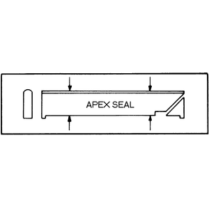
| Fig. 6: Apex seal height
|
- Use a micrometer to check the seal height.
- With a feeler gauge, check the side clearance between the apex seal and
the groove in the rotor. Insert the gauge until its tip contacts the bottom
of the groove. If the gap is greater than 0.0035 in. (0.09mm) for the 1983–85
12A engine, or 0.0059 in. (0.15mm) for the 1984–90 13B engine, replace
the seal. The standard range for non-turbo engines is 0.0024–0.0040
in. (0.06–0.10mm) and 0.0020–0.0040 in. (0.05–0.10mm) for
turbo engines.
- Check the gap between the apex seals and the side housing by using a vernier
caliper to measure the length of each apex seal. Compare this measurement
to the minimum figure obtained for the rotor housing width.
- Check the apex seal spring for wear and measure its free height. If less
than 0.2165 in. (5.5mm), replace the spring.
- If the seal is too long, sand the ends of the seal with emery cloth until
the proper length is reached. Do not use the emery cloth on the faces of the
seal.
- Check the side seal free movement in the rotor groove. You should be able
to press down along its length with your finger.
- Measure the side seal protrusion from the rotor surface. If the protrusion
is less than 0.02 in (0.5mm), replace the side seal spring.
- Measure the clearance between the side seal and its groove in the rotor
with a feeler gauge. (The standard clearance is given in the specification
chart, earlier in this section.) If the clearance is greater than 0.0039 in.
(0.10mm), replace the side seal.
- Using a feeler gauge, check the clearance between the side seal and the
corner seal when the seals are installed on the rotor. If the clearance is
greater than 0.0157 in. (0.4mm), replace the side seal. When installing a
new side seal, correct the clearance between the side and corner seals by
grinding the end of the side seal and the rounded corner seal with a fine
file. The clearance should be 0.0020–0.0059 in. (0.05–0.15mm).
If it exceeds this, the performance of the seals will deteriorate.
NOTE: There are 4 different types of side seals, depending
upon location. Do not mix up the seals and be sure to use the proper type
of seal for replacement.
- Inspect the corner seal and spring for wear, cracks, or damage and replace,
if necessary.
- Make sure the corner seal has free movement by pressing on it with your
finger.
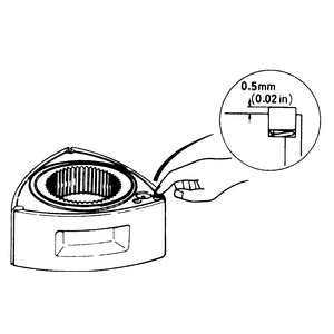
| Fig. 7: Corner seal protrusion
|
- Measure the corner seal protrusion from the rotor surface. It should protrude
at least 0.02 in (0.5mm). If not, replace the corner seal spring.
- Inspect the corner seal spring for wear.
Check the seal springs for damage or weakness. Be especially careful when checking
the spring areas which contact either the rotor or the seal.
- Wash the eccentric shaft in solvent and blow the oil passages dry with compressed
air.
- Check the shaft for wear, cracks, or other signs of damage. Make sure that
none of the oil passages are clogged.
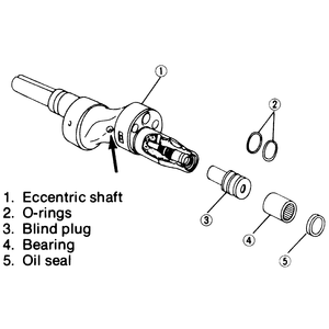
| Fig. 8: Exploded view of eccentric shaft. Remove
the oil jet plug (indicated by the arrow) to check the spring and
steel ball
|
- Measure the shaft journals. Replace the shaft if any of its journals show
excessive wear.
- Check eccentric shaft run-out. Rotate the shaft slowly and note the dial
indicator reading. Run-out should not exceed 0.0047 in. (0.12mm) as measured
from the end of the shaft. If run-out is greater than specification, replace
the eccentric shaft.
- Check the blind plug at the end of the shaft. If it is loose or leaking,
remove it with an Allen wrench and replace the O-ring.
- Check the operation of the needle roller bearing for smoothness by inserting
a mainshaft into the bearing and rotating it. Examine the bearing for signs
of wear or damage. Check the oil jet for spring weakness, sticking or ball
damage.
- Replace the bearings, if necessary, with special bearing replacer tools
49–0823–073 and 49–0823–072, or equivalent.
- Inspect the needle bearing for wear and damage.
- Inspect the bearing housing and the thrust plate for wear and damage.
- Lay the chain on a flat surface and check the entire length for broken links.
- Check the oil pump drive and driven sprockets for missing and broken teeth.
- Replace parts as necessary.

