Previous Next

INSTALLATION

  1. Make sure the cylinder bore and shaft journal are clean.
  2. Position the crankshaft journal at its furthest position away from the bottom of the cylinder bore.
  3. Coat the cylinder bore with light engine oil.
  4. Make sure the rod bearing shells are correctly installed. Slip a length of snug rubber hose over each rod bolt, to prevent the threads from damaging the shaft during installation.
  5. Check that the piston rings are installed with the end-gaps properly positioned. Install a ring compressor over the piston and rings, then compress the rings into their grooves. (Follow the ring compressor manufacturer's instructions.)
  6. Place the piston and connecting rod assembly into the cylinder bore. (If more than one piston was removed, make sure the assembly is in the proper bore.) Also, make sure that the piston and connecting rod are facing in the correct direction. Most pistons have an arrow or notch on the top of the piston, or the letter F appears somewhere on the piston, to indicate the side which faces the front of the engine.
  7. Check that the compressor is seated squarely on the block deck surface. If the compressor is not seated squarely, a ring could pop out from beneath the compressor and catch on the deck as the piston is tapped into its bore. Also, make sure the connecting rod is not hung up on the crankshaft counterweights, and is in position to engage the crankshaft.
  8. Tap the piston slowly into the bore, making sure the ring compressor remains squarely against the block. When the piston is completely in its bore, remove the compressor.
  9. Pull the connecting rod onto the crank journal, then remove the rubber hoses. Verify proper bearing fit by temporarily installing the rod cap with dry bearings and a Plastigage® insert. Check that the insert is not seated on an oil hole, and be sure the cap mark is aligned with the rod mark. Torque the connecting rod nuts to specification. Unfasten the connecting rod nuts, then remove the cap and the Plastigage® . Compare the insert's dimensions with specifications.

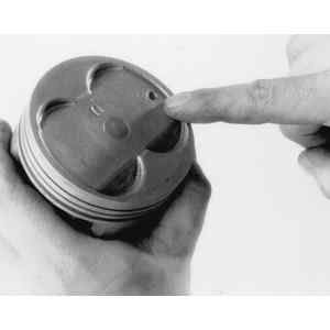
    Fig. 1: Most pistons are marked to indicate positioning in the engine. Usually, a mark indicates the side facing front

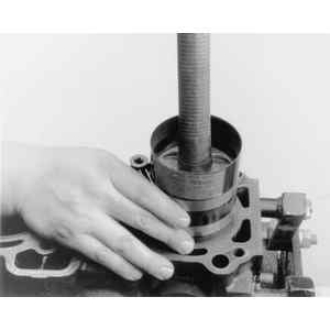
    Fig. 2: Installing a piston into the block using a ring compressor and hammer handle

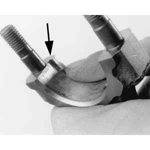
    Fig. 3: The notch on the side of the connecting rod matches the groove on the bearing insert

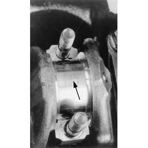
    Fig. 4: Apply a strip of gauging material to the bearing journal, before installing the cap

    Fig. 5: Install the connecting rod cap with matchmarks on the cap and rod aligned

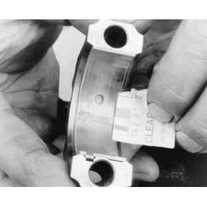
    Fig. 6: After removing the cap, compare the gauging material dimensions with clearance specifications

    NOTE: Even when the crankpin journal diameter surpasses minimum specifications, it is possible that bearing clearance is excessive. If the crankpin bearing oil clearance exceeds the maximum limit of 0.0039 in. (0.10mm), the journals must be machined and undersize bearings installed. If this work is necessary, it should be coordinated with a check of the crankshaft main bearings and journals, as well as end-play, as described later in this section.

  10. After verifying proper bearing fit, coat the crankshaft journal and connecting rod bearings with engine assembly lube or clean engine oil. Attach the connecting rod cap, then lightly oil the bolt threads and torque the nuts. Make sure the crankshaft rotates freely after each rod cap in torqued.
  11. Measure the clearance between the sides of the connecting rod itself (not the cap) and the crankshaft, with a feeler gauge. If the clearance is below minimum specifications, the connecting rod will have to be removed and machined. If the clearance is excessive, substitute an unworn rod and recheck. If clearance is still excessive, the crankshaft must be welded and reground, or replaced.
  12. If applicable, repeat Steps 1–11 for the other pistons.

Previous Next