

- Drain the cooling system and remove the air cleaner assembly. Remove the
oil dipstick.
- Disconnect the following:
- Throttle and choke linkage
- Fuel line(s)
- PCV valve hose
- Fuel and fuel pump hoses
- Heater hoses
- Distributor vacuum line
- Ventilation valve hose (at the manifold)
- Air pump hose at the anti-afterburn valve
- Brake vacuum hose
- Canister hoses
- Engine harness connectors
- Spark plug wires
- Remove the following components as required to gain access to the intake
manifold:
- Distributor
- Spark plugs
- Carburetor secondary air pipe manifold assembly
- Front engine hanger and ground wire
- Upper radiator hose and coolant bypass hose with mounting bracket
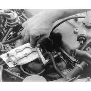
- Unfasten manifold attaching bolts and remove the manifold and gasket from
the cylinder head.
| Fig. 1: Remove the bolts securing the intake manifold
to the cylinder head (note that the carburetor may be left installed
on most models)
|
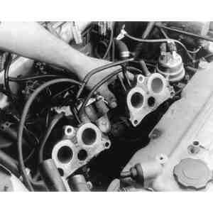
| Fig. 2: Withdraw the intake manifold from the cylinder
head
|
- Cover the ports on the cylinder block to prevent any foreign objects from
falling into the engine.
To install:
- Replace the gaskets, making sure all surfaces are clean and smooth. Check
manifold for warpage as described in the cylinder head overhaul procedures.
Repair if necessary.
- Install the manifold and, working from the center outward, tighten the bolts
gradually and in several stages, to specifications.
- Install the following components in the reverse order of removal as required:
- Coolant bypass hose and bracket
- Upper radiator hose
- Front engine hanger and ground wire
- Secondary air pipe manifold
- Spark plugs
- Distributor (see the beginning of this section for installation procedures)
- Connect the following components:
- Spark plug wires
- Engine harness connectors
- Canister hoses
- Vacuum hoses (including brake)
- Heater hoses
- Fuel pump and fuel hoses
- Accelerator and cruise control cables
- PCV valve hose
- Install the oil dipstick and refill the cooling system. Adjust all the linkages
and cables. Set the ignition timing and the idle speed, as described in Section
2.
CAUTION
Before removing the intake manifold, release the fuel system pressure. (See
Section 5 for details.)
- Disconnect the negative battery cable and drain the cooling system.
- Disconnect the accelerator cable from the throttle body. Label and disconnect
all air and vacuum hoses from the dynamic chamber and the throttle body.
- Loosen the hose clamps, then disconnect the air funnel from the air flow
meter and the throttle body. On turbocharged engines, disconnect the air funnel
from the throttle body and the intercooler.
- Disconnect the spark plug wires from the distributor and unplug the connector
from the ignition coil. Loosen the hose clamp on the flexible hose and disconnect
the hose from the air cleaner assembly. Unfasten the bolts from the air cleaner
cover and remove the air cleaner/air flow meter assembly from the vehicle.
- Disconnect the water hoses and the throttle sensor connector. Remove the
retaining nuts and bolts from the throttle body, then separate the throttle
body from the intake manifold.
- Disconnect the hoses and remove the BAC valve. On turbocharged engines,
disconnect the water hose for the oil cooler and plug the opening to prevent
leakage.
- On turbocharged engines, unbolt the intake manifold and dynamic chamber
assembly from the cylinder block, then lift it out of the vehicle.
- On non turbocharged engines, unbolt the dynamic chamber from the intake
manifold and remove it along with the gasket, then remove the intake manifold.
- Remove the intake manifold gasket from the cylinder block. Cover or plug
the intake ports to prevent anything from falling into the engine.
- Thoroughly clean the intake manifold and cylinder block gasket mating surfaces.
Visually inspect the intake manifold and dynamic chamber for cracks.
To install:
- Place a new gasket on the cylinder block and lower the intake manifold onto
the gasket. On turbocharged engines, attach the dynamic chamber to the intake
manifold with a new gasket. Install the retaining nuts and bolts and torque
them to 14–19 ft. lbs. (19–26 Nm).
- Install the remaining components in the reverse order of removal:
- Oil cooler water hose (turbocharged engines)
- BAC valve and hoses
- Throttle body (with new gasket) and throttle sensor connector
- Water and vacuum hoses
- Air cleaner/air flow meter assembly, spark plug wires and distributor
connector
- Air funnel
- Accelerator cable
- Refill the cooling system to the proper level and connect the negative battery
cable. Check the accelerator cable deflection.
CAUTION
Before removing the intake manifold, release the fuel system pressure. (See
Section 5 for details.)
- Disconnect the negative battery cable and drain the cooling system.
- Unplug the air flow meter connector. Disconnect the air cleaner duct (1987
only), secondary air hoses and air control vacuum hoses, then remove the air
cleaner. On 1988–89 models, disconnect and remove the air duct along
with the No. 1 resonance chamber.
- Remove the air flow meter and attendant air hoses. On 1988–89 non-turbocharged
engines, the No. 2 resonance chamber is connected to the bottom of the flexible
air hose by a small hose with a hose clamp, and is retained by one attaching
screw. Disconnect and remove the No. 2 resonance chamber.
- On 1988–89 turbocharged engines, trace the upper hose on the intercooler
to the air bypass valve. (There are three hoses connected to the valve.) Loosen
the hose clamps and disconnect the hoses. Unbolt and remove the air bypass
valve from its mounting bracket, then remove the intercooler.
- Unfasten the electrical connectors from the throttle body. Disconnect the
water and vacuum hoses, then plug the openings.
- Disconnect the accelerator cable from the throttle body and remove the throttle
body (with gasket) from the dynamic chamber.
- Disconnect the PCV hose and the vacuum pipe assembly. Remove the nuts and
bolts that attach the dynamic chamber to the intake manifold and remove it
along with the gasket.
- Unfasten connectors from the fuel injectors, then route the wiring harness
off to the side and out of the way. Disconnect the fuel hose from the injector
rail and remove the rail assembly with the injectors attached. Plug all the
fuel openings.
- Disconnect the remaining vacuum hoses and remove the EGR pipe.
- Remove the intake manifold bracket, followed by the intake manifold and
gasket. Cover or plug the intake ports with clean rags or masking tape to
prevent anything from falling into the engine.
- Thoroughly clean the intake manifold and cylinder block gasket mating surfaces
with a gasket scraper and solvent. Visually inspect the intake manifold and
dynamic chamber for cracks.
To install:
- Place a new gasket on the cylinder block and lower the intake manifold onto
the gasket. Install the retaining nuts and torque them to 14–22 ft.
lbs. (19–30 Nm).
- Install the remaining components in the reverse order of removal:
- Intake manifold bracket
- EGR pipe and vacuum hoses
- Fuel rail and injector harness assembly
- Dynamic chamber with new gasket
- Vacuum pipe assembly and PCV hose
- Throttle body with new gasket
- Accelerator cable
- Vacuum and water hoses
- Throttle body connectors
- Intercooler
- Air bypass valve with hoses
- No. 2 resonance chamber (1988–89 non-turbocharged models only)
- Airflow meter
- No. 1 resonance chamber
- Air duct, air cleaner and air flow meter connector
- Refill the cooling system to the proper level and connect the negative battery
cable. Check the accelerator cable deflection.
CAUTION
Before removing the intake manifold, release the fuel system pressure. Please
refer to Section 5 for details on releasing the fuel system pressure.
- Disconnect the negative battery cable. Disconnect the coolant hoses and
plug them. (The coolant will be drained from the radiator just before the
intake manifold is ready to be removed.)
- Disconnect the air inlet duct from the air cleaner and unplug the air flow
meter connector.
- Locate the two solenoid valves (TICS and purge air control) that are bolted
to the front of the air cleaner. Label and disconnect the vacuum hoses.
- Remove the air cleaner assembly, air flow meter and air funnel.
- Disconnect the Bypass Air Control (BAC) valve connector and coolant hoses,
then remove the valve.
- Disconnect the throttle sensor connector and the accelerator cable. Remove
the throttle body and gasket.
- Disconnect all vacuum hoses, EGR pipe, EGR position sensor connector, coolant
hose and ground wire.
| Fig. 3: Intake manifold loosening sequence — 929
|
| Fig. 4: Intake manifold tightening sequence — 929
|
- Remove the wiring harness bracket.
- Disconnect the air intake pipe from the dynamic chamber with the gasket.
- Mark the extension manifolds RIGHT and LEFT for assembly reference, as they
are not interchangeable. Remove the six extension manifolds with their gaskets
from the dynamic chamber.
- Disconnect the intake air thermosensor connector, vacuum hoses and ground
connectors.
- Remove the attaching nuts and lift the dynamic chamber straight up from
the intake manifold studs. Drain the radiator at this time and disconnect
all remaining connectors, fuel hoses, and coolant hoses.
- Using the sequence shown in the illustration, loosen the intake manifold
nuts in two stages. Lift the intake manifold from the engine and remove the
two intake manifold gaskets. Insert clean rags into the intake ports or cover
them with masking tape to prevent anything from falling into the engine.
- Immerse the intake manifold in a suitable solvent and blow it dry with compressed
air. Visually inspect the intake manifold for cracks, warpage or any other
type of damage and replace as necessary. Remove all gasket material from the
seating surface on the manifold and the engine. Forward of one of the studs
that secures the dynamic chamber is an O-ring that seals the manifold to the
dynamic chamber. Remove this O-ring and replace it with a new one.
To install:
- Place the new intake manifold gaskets onto the cylinder block and lower
the manifold over the gaskets. Install the intake manifold washers with the
white paint marks facing up. Install the retaining nuts and torque them in
two stages to 14–18 ft. lbs. (19–24 Nm) using the sequence shown
in the illustration.
- Install the remaining components in the reverse of the removal procedure:
- Connectors, fuel hoses, coolant hoses and vacuum hoses.
- Dynamic chamber. Torque the retaining nuts to 14–18 ft. lbs. (19–24
Nm)..
- Intake air thermosensor ground connectors and vacuum hoses.
- Extension manifolds with new gaskets and O-rings.
- Intake air pipe with new gaskets and wiring bracket.
- Ground wire, coolant hose, EGR position connector, EGR pipe and vacuum
hoses.
- Throttle body with new gasket, accelerator cable and throttle sensor
connector. Check the deflection of the accelerator cable. If not within
0.04–0.12 in. (1–3mm), adjust with the nuts on the cable bracket.
- BAC valve, coolant hoses and connector.
- Air funnel, air hoses, air flow meter, and air cleaner assembly.
- TICS and purge control solenoid valves, air flow meter connector, vacuum
chamber and air duct.
- Make sure that all hose connections are tight, then refill the cooling system
to the proper level. Connect the negative battery cable. Start the engine
and check for leaks.