Previous Next

PISTON ASSEMBLY

  1. If applicable, pistons and rods must be assembled (piston pins installed) with rods facing in the proper direction. With the F mark on the piston facing you, turn the connecting rod so the oil hole which lubricates the cylinder is on the left. On 1979–82 626 engines, the rod is assembled with the connecting rod bolt heads pointing to the right, as shown. The piston pin (and other related parts) must be thoroughly lubricated with clean engine oil and pressed in from the F mark side. On the 1.3L engine, heat the piston slightly if the pin is a tight fit, press it into the piston, and install new circlips.

    Fig. 1: Piston and connecting rod assembly — except 1979–82 2.0L (Code MA) engine

    Fig. 2: On 1979–82 2.0L (Code MA) engines, the connecting rod bolt heads angle to the right

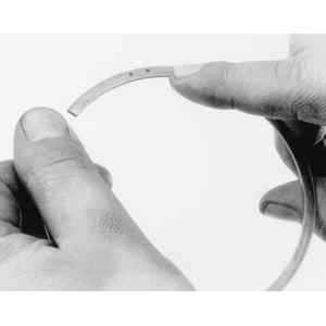
    Fig. 3: Installing the oil control ring's upper rail

    Fig. 4: Most rings are marked to show which side faces upward

    Fig. 5: Stagger the positions of the ring gaps around the piston as shown

    Fig. 6: Using the piston pin as a baseline, upper and lower compression ring openings should each be offset 30°in opposite directions. The oil control ring's upper and lower rails should also be offset

    NOTE: On gasoline engines, other than the 1.3L engine, this job requires special tools and a press that can apply and measure 1,100–3,300 lbs. (500–1,500 kg) of force. If it requires less than 1,100 lbs. (500 kg) to insert the pin, the pin or connecting rod must be replaced.

  2. On the 2.0L (Code FE), 2.2L and 3.0L engines, the completed assembly must pass the connecting rod oscillation torque test previously described. If the rod does not descend freely, replace the piston and/or piston pin.
  3. Install the three-piece oil control ring with its rails and grooves thoroughly lubricated. Start with the oil control ring spacer (expander). Next, install the oil control upper rail by inserting one edge between the groove and spacer, and holding it in place with your thumb. Then, run your other thumb along the edge of the rail to work it into the groove. Install the lower rail similarly. Check that both rails are expanded by the spacer tangs, so that they turn smoothly in both directions.

    NOTE: On many engines, the upper and lower rails are identical, and can be installed with either face upward.

  4. Install the lower (second) compression ring, followed by the upper ring, with R or RN markings facing upward. Use a ring expander, but open the rings as little as possible. When the rings are installed, oil them and stagger their gaps as shown in the illustrations, to prevent excessive oil consumption and loss of compression.

Previous Next