WARNING
This operation should only be performed when the engine is cold!
NOTE: Although the cylinder head need not be removed, the same bolts which retain the cylinder head to the block also secure the rocker shaft assembly.
| Fig. 1: Cylinder head bolt loosening sequence — 1.3L,
1.4L, 1.5L and 1979–82 2.0L engines
|
| Fig. 2: Position the rocker assembly on 1979–82
2.0L engines so that the oil passages align as shown
|
| Fig. 3: On 1978–85 GLCs and 1979–82 626s,
position the rocker assembly so that the adjusting studs are offset
0.039 in. (1mm) from the centers of the exhaust valve stems
|
| Fig. 4: Cylinder head bolt tightening sequence — 1.3L,
1.4L, 1.5L and 1979–82 2.0L engines
|
To install:
NOTE: Do not remove the rocker shaft bolts.
| Fig. 5: Rocker shaft bolt loosening sequence — 1.6L
engine
|
| Fig. 6: Rocker shaft bolt loosening sequence — 2.2L
and 1983–87 2.0L engines
|
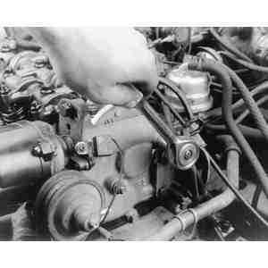
| Fig. 7: If applicable, unfasten the retaining nuts
and bolts . . .
|
| Fig. 8: . . . then remove the rear housing and gasket
|
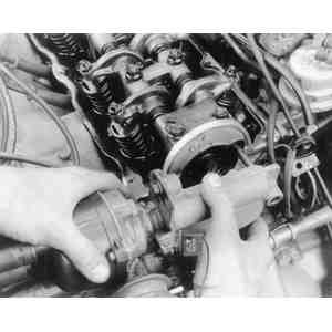
| Fig. 9: Loosen (but do not withdraw) the rocker shaft
bolts, then lift the shaft assembly from the head
|
| Fig. 10: On 2.2L and 1983–87 2.0L engines,
coat each end of the cylinder head with sealer (as indicated by the
shaded areas), before installing the rocker shaft assembly
|
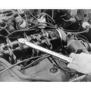
| Fig. 11: After positioning the rocker shaft assembly,
tighten the bolts to specification
|
| Fig. 12: Rocker shaft bolt tightening sequence — 1.6L
engine
|
| Fig. 13: Rocker shaft bolt tightening sequence — 2.2L
and 1983–87 2.0L engines
|
To install:
NOTE: The following procedure applies to both cylinder banks.
NOTE: Do not remove the rocker shaft bolts.
| Fig. 14: Rocker arm shaft loosening sequence — 3.0L
engine
|
| Fig. 15: Rocker arm shaft tightening sequence — 3.0L
engine
|
To install: