

- Check the air pump drive belt tension by applying 22 lbs. (10 kg) of pressure
halfway between the water pump and air pump pulleys. The belt should deflect
0.28–0.35 in. (7–9mm). Adjust the belt if necessary, or replace
if it is cracked or worn.
- Remove the belt and turn the pump by hand. If it has seized, the pump will
be very difficult or impossible to turn.
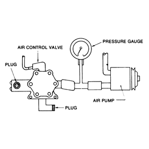
| Fig. 1: Test connections for the RX-7's air pump
|
NOTE: Disregard any chirping, squealing or rolling sounds
coming from inside the pump; these are normal when it is being turned by
hand.
- Check the hoses and connections for leaks. Soapy water, applied around the
area is question, is a good method of detecting leaks.
- Connect a pressure gauge between the air pump and the air control valve
with a T-fitting.
| Fig. 2: After confirming the air pump's operation,
disconnect the pressure gauge from the air control valve and seal
off the T-fitting — RX-7

|
- Plug the other hose connections (outlets) on the air control valve, as illustrated.
A gauge set which is similar to the illustrated rig (Mazda Part No. 49–2113–010B
or equivalent) is available to test the air pump.
CAUTION
Be careful not to touch the thermal reactor/exhaust manifold; severe burns
will result.
- Connect a tachometer to the engine and check the idle speed. If the idle
speed is not within specifications, adjust as necessary. With the engine at
800 rpm, the pressure gauge should read 1.64 psi (3.34 in. Hg). Replace the
air pump if it is less than this.
- If the air pump is not defective, leave the pressure gauge connected, but
unfasten the connections at the air control valve and plug or cap the T-fitting,
as shown, before proceeding with the next test.
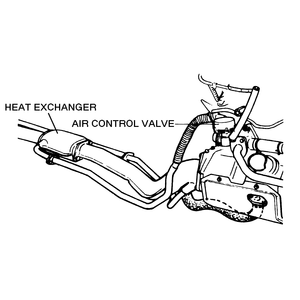
The air control valve on 1979–80 models consists of three valves: No.
1 relief valve, No. 2 relief valve, and an anti-afterburn valve. The No. 1 relief
valve controls the flow of cooling air to the thermal reactor and is controlled
by air pump air pressure. The No. 2 relief valve controls fresh air flow into
the exhaust ports when closed, and re-routes excess fresh air back into the
air cleaner when open. The anti-afterburn valve allows additional air into the
intake manifold to prevent afterburn when the ignition is turned OFF.
| Fig. 3: Location of the air control valve — 1979–80
RX-7
|
Testing of the air control valve is performed as follows:
- Check all hoses and vacuum sensing tubes for loose connections and damage.
Make sure the air pump drive belt is properly adjusted.
- Check that the air control valve is attached to the carburetor tightly.
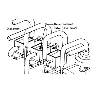
| Fig. 4: Disconnect the vacuum sensing tube from the
relief solenoid valve — RX-7
|
| Fig. 5: Check the air control valve by placing a
piece of paper in front of it — 1979–80 RX-7

|
- Connect a tachometer to the engine, and disconnect the vacuum sensing tube
from the relief solenoid valve.
NOTE: The relief solenoid valve has a blue dab of paint
on its body.
- Disconnect the air hose between the air cleaner and the air control valve
at the air cleaner, then start the engine and run it at idle.
- Place a finger over the air hose opening and verify that air does not flow
out of the opening.
- Reconnect the vacuum sensing tube to the relief solenoid valve and gradually
increase engine speed. Air should start to flow out of the air hose when the
engine speed reaches about 1,300 rpm.
- Stop the engine and remove the air pipe between the air control valve and
the thermal reactor. It will be warm, so wait a few minutes and be careful.
- Start the engine and run it at idle. Check to see that air does not flow
out from the air control valve by placing a piece of paper in front of the
valve, as shown in the illustration.
- Increase engine speed to 4,500 rpm; air should flow out of the air control
valve.
If the results for any of these tests differ from the information given
here, the air control valve is not working properly and should probably
be replaced.
The air control valve consists of an air relief valve, an air switching valve
and a No. 1 anti-afterburn valve. The air relief valve controls fresh air flow
into the exhaust ports when closed, and re-routes excess fresh air back into
the air cleaner when open. The air switching valve switches the flow of fresh
air back and forth between the exhaust ports and the two-bed catalyst according
to engine demand. The anti-afterburn valve allows additional air into the intake
manifold to prevent afterburn when the ignition is turned OFF.
- Check that all solenoid valve connections are tight and that the air pump
drive belt is adjusted properly.
- Make sure the air control valve is firmly attached to the engine.
- Connect a tachometer to the engine. Disconnect the relief solenoid valve
vacuum sensing tube and connect the tube to a suitable vacuum source.
NOTE: The relief solenoid valve has a blue dab of paint
on its body.
- Disconnect the hose running from the air control valve to the air cleaner
at the air cleaner.
- Start the engine and run it at idle; no air should be flowing through the
hose when the choke is off and the engine is warm.
- Slowly raise the engine rpm. Air should now begin to flow through the hose
when the vacuum is removed from the sensing tube.
- Reconnect the vacuum source to the relief solenoid valve vacuum sensing
tube.
- Set the engine speed to 2,500 rpm with the throttle, and disconnect the
vacuum sensing tube from the switching solenoid valve (gray painted valve);
air should flow through the air hose. Air should stop flowing when this vacuum
tube is reconnected.
The air control valve functions to direct intake air to one of three locations:
exhaust port, main converter, or relief air silencer. The air control valve
system consists of the relief valve, switching valve and anti-afterburn valve.
- Warm up the engine to normal operating temperature. Connect a tachometer
to the engine and check/adjust the idle speed.
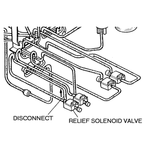
| Fig. 6: Relief solenoid valve location — 1986–89
non-turbo RX-7
|
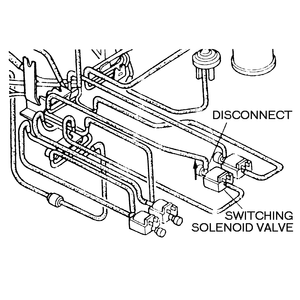
| Fig. 7: Switching solenoid valve location — 1986–89
non-turbo RX-7
|
NOTE: On 1987–89 turbocharged vehicles equipped with
ABS, disconnect the air and vacuum hoses on the air control valve from the
turbocharger. Plug the ends of the hoses before disconnecting the air control
valve hose in the next step.
- Disconnect the hose that runs from the air silencer to the air control valve
at the valve.
- Place a finger over the air control outlet port.
- Have an assistant gradually increase the engine speed to 1,500–2,500
rpm for 1984–89 non-turbo vehicles, or 3,750–3,850 rpm for 1986–89
turbocharged vehicles.
- Run the engine at idle speed.
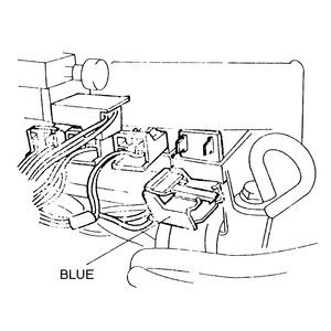
| Fig. 8: Relief solenoid valve connector — 1986–89
RX-7 turbo
|
- On 1984–89 non-turbocharged models, locate the vacuum hose that runs
between the relief solenoid valve and the air control valve. Disconnect the
hose from the relief solenoid valve. On 1986–89 turbocharged vehicles,
unfasten the relief solenoid valve connector.
NOTE: The relief solenoid valve is identified by a blue
tab or blue dab of paint on some models.
- Make sure air flows from the relief solenoid valve at 1,200 rpm or greater.
Reattach the vacuum hose or the electrical connector.
- Locate the split air hose that runs from the intake manifold to the check
valve. Disconnect the hose from the check valve and place a finger over the
port. Disconnect the vacuum hose from the switching solenoid valve.
- Make sure air flows from the switching solenoid valve port.
- If air flow is not as described, replace the air control valve.
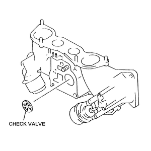
The check valve prevents exhaust gases from traveling backwards into the air
pump and damaging it. There are two check valves used in the secondary air injection
system. One is installed in the intake manifold, and the other is located inline
between the intake manifold and catalytic converter. Both check valves are tested
the same way and perform the same protective function.
- Warm the engine to normal operating temperature, and connect a tachometer
to the engine.
| Fig. 9: Intake manifold-mounted check valve — 1985–87
fuel injected RX-7
|
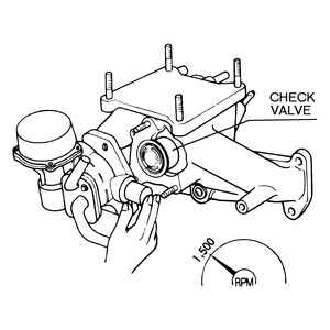
| Fig. 10: Exhaust gas leakage at the air control valve's
air inlet indicates a defective check valve
|
- Disconnect the hose between the air pump and the air control valve at the
air control valve. Disconnect the switching solenoid valve coupler (1981 models).
If testing the catalytic converter check valve, locate the hose that runs
from the intake manifold to the converter at the rear of the intake manifold,
and disconnect it.
- Slowly increase the engine speed to 1,500 rpm and watch for exhaust gas
leakage at the air inlet fitting on the air control valve. If exhaust gas
is coming out of the inlet, replace the check valve.

