There are several things to check if a malfunction of the evaporative emission
control system is suspected.
- Leaks may be traced by using an infrared hydrocarbon tester. Run the test
probe along the lines and connections. The meter will indicate the presence
of a leak by a high hydrocarbon (HC) reading. This method is much more accurate
than a visual inspection, which would indicate only the presence of a leak
large enough to pass liquid.
- Leaks may be caused by any of the following, so always check these areas
when looking for them:
- Defective or worn lines
- Disconnected or pinched lines
- Improperly routed lines
- A defective check valve
NOTE: If it becomes necessary to replace any of the
lines used in the evaporative emission control system, use only those
hoses which are fuel resistant or are marked EVAP.
- If the fuel tank has collapsed, it may be the fault of clogged or pinched
vent lines, a defective vapor separator, or a plugged or incorrect check valve.
NOTE: This test requires the use of a precisely calibrated
pressure gauge and a source of compressed air. If you do not have these items
on hand, it may be advisable to go to a professional for testing.
- Start out by testing the No. 1 and No. 2 purge control valves, as described
in Steps 6 and 7 of the procedure for the 626/MX-6, which follows.
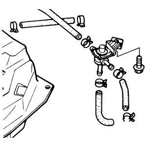
| Fig. 1: Check and cut valve removal — carbureted
323
|
- Remove the air cleaner. Place a finger on top of the air vent solenoid valve,
located on top of the carburetor. Have someone turn the ignition switch ON and OFF as
you feel for operation of the solenoid. If the solenoid does not click audibly
or operate so that you can feel it, replace the valve.
- Test the water temperature valve, as described in Step 3 of the 626/MX-6
procedure. Replace the valve if it fails the test.
- Remove the check and cut valve, noting that the horizontal connection goes
to the fuel tank and the vertical connection is vented to the air. Tee a pressure
gauge into the horizontal passage (normally connected to the tank). Hold the
valve horizontally for proper internal air flow. Gradually admit air into
the valve while watching the pressure. Air should start to flow through the
valve at 0.14–0.71 psi (0.98–4.9 kpa). Connect the gauge to the
vertical (vented) connection. Again, gradually admit air into the valve while
watching the pressure. It should open at 0.78–1.00 psi (5.39–6.87
kpa). Replace the valve if it fails either test.
- Test the vacuum switching valve, as described in Step 8 of the 626/MX-6
procedure.
- Disconnect the vacuum delay valve. Connect the vacuum pump to the end of
the valve away from the arrow with a length of hose 40 in. (1 meter) long.
Draw a vacuum of 24 in. Hg. Then, watch as the vacuum decreases from 19.7
in. Hg to 3.9 in. Hg, timing how long it takes. It should take 0.2–1.2
seconds. If the valve fails the test, replace it.
- Warm up the engine and allow it to run at idle speed.
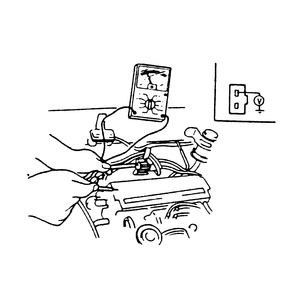
- Connect a voltmeter to the Y terminal of the No. 1 purge
control solenoid valve, located at the top of the canister. You should read
approximately 12V on the meter.
- Disconnect the vacuum hose from the No. 1 purge control valve and place
a finger over the opening of the hose.
| Fig. 2: Checking No. 1 purge solenoid "Y'' terminal
voltage — fuel injected 323
|
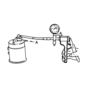
| Fig. 3: Checking No. 1 purge control valve — fuel
injected 323
|
- Increase the engine speed to 2,000 rpm and make sure that no air is being
sucked into the hose.
- On vehicles equipped with a manual transaxle, detach the neutral switch
connector and connect a jumper wire across the terminals. On automatic transaxle-equipped
vehicles, detach the inhibitor switch connector. Check the Y terminal
voltage as described in Step 2.
- Place your finger over the vacuum hose, then increase the engine speed to
2,000 rpm and make sure that no air is being sucked into the hose. If there
is a vacuum, check the engine control unit's 2P terminal, then check the No.
1 purge control solenoid and control valves, as described in Steps 7 and 8.
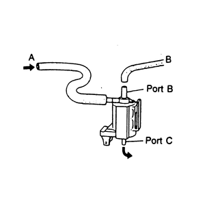
| Fig. 4: Checking No. 1 purge solenoid valve air flow — fuel
injected 323
|
- To check the No. 1 purge control valve, blow through the purge control valve
from port A, as shown in the illustration, and make sure that
no air passes through it. Then, connect the vacuum pump to the purge control
valve, also as shown in the illustration. Apply a vacuum of 4.33 in. Hg to
the purge control valve, then repeat the attempt to blow air into port A.
At this time, air should pass freely through port A. If not, replace
the valve.
- To check the No. 1 purge solenoid valve, disconnect the vacuum lines from
ports A and B on the solenoid. Detach the
electrical connector from the bottom of the solenoid. Blow into port A and
verify that air comes out of port C. Apply battery voltage to
the solenoid with a jumper wire, then blow into port A and
verify that air passes freely from port B. If the valve does not
function as described, replace. Proceed with the remainder of the procedure
to finish the emission control system inspection.
- Fasten the neutral or inhibitor switch connector, depending on the type
of transaxle.
- Disconnect the vacuum hose leading directly to the canister (not passing
through the purge valve). Disconnect the rubber hose at the canister, then
connect a vacuum source to the open end of the hose, so that air will be drawn
out of the steel pipe mounted to the car body. Operate the vacuum pump. Air
should be drawn into the pump freely. If the system holds vacuum, inspect
the pipe or the three-way check valve (located near the fuel tank) for clogging.
- Warm up the engine, then let it idle. Disconnect the vacuum hose leading
to the purge control valve on top of the canister. Connect a vacuum gauge
or special tester 49-9200-750A, or equivalent, to the open end of the hose.
Connect a tachometer to the ignition system.
- Increase the engine rpm to 2,500 and read the vacuum gauge. Vacuum must
be a minimum of 5.9 in. Hg. If the vacuum is okay, go to Step 4. Otherwise,
test the water temperature valve as described in Step 3.
| Fig. 5: Disconnect vacuum hose "B'' from the No.
3 purge control valve and plug it — 1986–89
626 and MX-6

|
- Drain some coolant out of the system, then unscrew the water temperature
valve from the intake manifold. Connect two short lengths of vacuum hose to
the valve's connection points. Immerse the lower portion of the valve in a
container of water with the vacuum hoses above the liquid level. Immerse a
suitable thermometer in the water, then heat the water to more than 130°F
(54°C) and attempt to blow air through the valve. If air passes, the
valve is okay; otherwise, replace it. Reconnect the vacuum hose.
- Disconnect the vacuum hose labeled B from the No. 3 purge
control valve and plug it. Then, with another length of hose, connect a vacuum
gauge to the open port in the purge control valve, as shown. Run the engine
to more than 1,500 rpm and check for vacuum. If there is no vacuum, inspect
the three-way solenoid valve, the No. 3 purge control valve and the EGR control
unit's 2P terminal. Disconnect the vacuum gauge and reconnect the vacuum hose.
- Disconnect the vacuum hose leading directly into the canister (not passing
through the purge valve). Disconnect the hose at the canister, then connect
a vacuum source to the open end of the rubber hose, so that air will be drawn
out of the steel pipe mounted to the car body. Operate the vacuum pump. Air
should be drawn into the pump freely. If the system holds vacuum, inspect
the pipe or the three-way check valve (located near the fuel tank) for clogging.
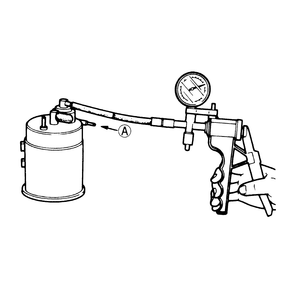
- Attempt to blow air into the port labeled A. No air should pass
into it. Connect the vacuum pump to the purge control valve, as shown in the
illustration. Apply a vacuum of 4.33 in. Hg to the purge control valve. Then,
repeat the attempt to blow air into A. This time, air should flow.
Otherwise, replace the purge control valve.
| Fig. 6: Blow into port "A'' to begin inspection of
the No. 1 purge control valve — 1986–89 626
and MX-6
|
| Fig. 7: Testing the three-way check valve — 1986–89
626 and MX-6
|
- Disconnect the hose referred to in Step 5 at the metal pipe, but this time,
blow into the hose with it still connected to the canister. Air should flow
freely. Otherwise, replace the No. 2 purge valve.
- First, label the connecting hoses, then remove the No. 3 purge control valve.
Blow into the center port on the flat side of the valve and check for air
flow leaving the outboard port on the flat side. There should be no air flow
without vacuum being applied to the valve. Apply vacuum of 2.95 in. Hg to
the single port located on the convex side of the valve. Then, blow through
the center port again, as you did at the beginning of this step. Air should
now flow out of the outboard port. Install a new valve, if necessary, or reinstall
the old one with all hoses properly connected, according to your labeling.
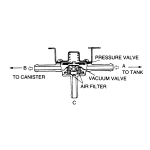
- Remove the three-way check valve located on the gas tank vent line near
where the filler pipe connects with the fuel tank. Blow through Port A and
make sure air comes out Port B. Seal off Port B and
blow again from Port A. Air should flow out of Port C.
Now, block Port B and blow through port C. Air
should come out of Port A. If the valve fails any of these tests,
replace it.
- The three-way solenoid valve is located at the right of the three valves
mounted on the fender well. Label, then disconnect the two hoses at the bottom
of the valve. Connect a short length of hose to the port leading into the
side of the valve near the bottom, leaving the vertical port (which discharges
out in a downward direction) open. First, blow through the hose and check
for discharge of air through the filter at the top. Then, energize the valve
by applying battery voltage to the electrical connector at the top with a
jumper wire. Now, when you blow through the hose, air should be discharged
through the port at the bottom of the valve. If the valve fails either test,
replace it.
When the car is parked after operation for some distance, the fuel in the float
chamber tends to evaporate and enter the intake manifold through an inner air
vent. This, in turn, causes the fuel mixture to become too rich and flood the
engine. To prevent this chain of events, an air vent solenoid valve is installed
on the carburetor. When the engine is not running (ignition switch in the OFF position),
a plunger attached to the air vent solenoid is pulled out, which allows the
fuel vapors in the float bowl to be fed into the charcoal canister, where they
are stored. When the engine is running (ignition switch turned ON),
the solenoid closes. This opens the air vent in the carburetor and closes off
the passage to the charcoal canister. Testing of the air vent solenoid valve
is performed as follows:
- Check the air vent hose for cracking or other damage.
- Disconnect the air vent hose from the ventilation pipe.
- Slowly blow through the hose and make sure that air passes through the air
vent solenoid valve.
- Turn the ignition switch to the ON position.
- Slowly blow through the hose; air should not pass through the air vent solenoid.
If it does, check the solenoid wiring or replace the solenoid.
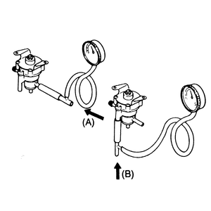
- Disconnect and remove the check and cut valve, as described below.
NOTE: Perform the test with the valve held horizontally.
Otherwise, the weight of the valve will cause it to move out of position
and close the passage.
| Fig. 8: Testing the check and cut valve — fuel
injected RX-7
|
- Connect a pressure gauge to the passage from the fuel tank (port A).
- Blow into the valve through port A. Check that the valve opens
at 0.14–0.71 psi (0.97–4.90 kpa).
- Remove the pressure gauge and connect it to the passage that vents to the
atmosphere (port B).
- Blow into the valve through port B and check that the valve
opens at 0.78–1.00 psi (5.38–6.89 kpa).
- If the valve does not function as described, replace it.
- Disconnect and remove the check and cut valve.
- Blow into the valve through port A and make sure that air
comes out of port B.
- Block port B and confirm that air comes out of port C.
- Block port B and draw air through port A. Air
should pass through from port C.
- If the valve does not function as described, replace it.

