NOTE: This adjustment can be performed only with the carburetor
removed from the engine.
- Close the choke valve fully, and measure the clearance between the lower
edge of the throttle and the throttle bore with a wire feeler gauge. The dimension
is 0.05–0.06 in. (1.2–1.5mm).
- If necessary adjust by bending the rod which connects the choke shaft and
fast idle cam.
- On the 1.4L GLC engine, remove the bimetal cover.
- Using your finger close the choke valve fully.
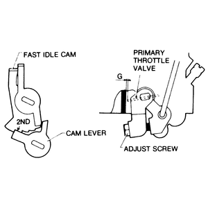
| Fig. 1: Fast idle cam adjustment — 1.4L
engine
|
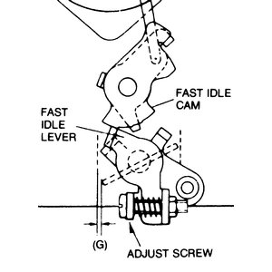
| Fig. 2: Fast idle cam adjustment — 2.0L
engine
|
- Make sure the fast idle cam is on the 1st position (3rd position for the
1.5L GLC engine).
- The throttle valve opening (clearance G) should be:
- 1.4L engine: 0.06 in. (1.4mm) in 1979; 0.04 in. (1.04mm) in 1980
- 1.5L engine: 0.03 in. (0.66mm)
- 2.0L engine: 0.04 in. (1.04mm) in 1979; 0.02 in. (0.61mm) for 1980–82
- Adjust by turning the adjustment screw.
NOTE: Turn the adjustment screw clockwise to increase the
clearance.
NOTE: To adjust the fast idle, it is necessary for the carburetor
to be removed from the car.
- Remove the carburetor from the vehicle.
- Fully close the check valve.
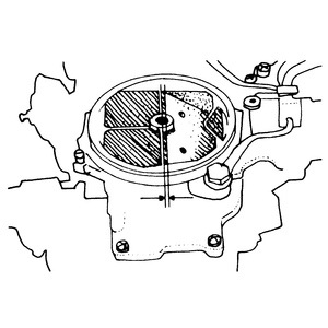
| Fig. 3: Fast idle adjustment — RX-7
|
- Measure the clearance between the primary throttle valve and the wall of
the throttle bore. Clearances are as follows:
- 1979 (California) and 1980 — 0.05–0.06 in. (1.30–1.50mm)
- 1979 (49 states, Canada) and 1981 — 0.035–0.043
in. (0.90–1.10mm)
- 1982 (All models) — 0.03–0.04 in. (0.8–1.0mm)
- 1983–85 (All models) — 0.04–0.05 in. (1.0–1.2mm)
- If clearance is not correct, bend the fast idle rod until proper clearance
is obtained.
- Invert the air horn and lower the float slowly until the seat lip just touches
the needle valve. Measure the clearance between the float and air horn gasket
surface (remove the gasket). It should be 0.43 in. (11mm). Bend the float
seat lip as necessary to correct the dimension.
- With air horn still inverted, lift the float upward until the float stop
contacts the air horn. Measure the clearance between the top of the needle
valve and the float seat lip. It should be 0.05–0.07 in. (1.3–1.7mm).
If not, bend the float stop until the clearance is correct.
- Invert the air horn and allow the float to lower by its own weight.
- Measure the clearance between the float and the air horn bowl. The clearance
should be 0.43 in. (11mm). Bend the float seat lip to adjust.
- Turn the air horn to the normal position and allow the float to lower by
its own weight.
- Measure the distance between the bottom of the float and the air horn bowl.
The distance should be 1.8 in. (46mm). Bend the float stopper to adjust.
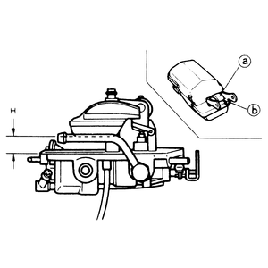
- Invert the air horn and allow the float to lower by its own weight.
- Measure the clearance between the float and the air horn bowl. The clearance
should be 0.53 in. (13.5mm). Bend the float seat lip to adjust.
| Fig. 4: Float-to-air horn bowl adjustment (clearance
"H") — 1983–87 626
|
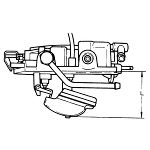
| Fig. 5: Float bottom-to-air horn bowl adjustment
(clearance "L") — 1983–87 626
|
- Turn the air horn to the normal position and allow the float to lower by
its own weight.
- Measure the distance between the bottom of the float and the air horn bowl.
The distance should be 1.93 in. (49mm). Bend the float stopper to adjust.
The float bowl fuel level can be checked through the sight glass in the carburetor
body. Fuel level should be in the center of the glass. Be sure to check the
level of both float chambers.
- Remove the air cleaner and remove the top part of the carburetor (the air
horn).
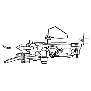
- Turn the air horn upside down and allow the float to rest, as shown in the
illustration. Measure clearance H between the float and the
air horn gasket. Clearance should be 0.61–0.65 in. (15.5–16.5mm).
If clearance is not correct, bend the float seat lip as required to adjust.
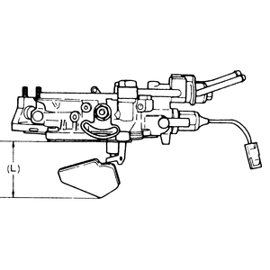
- Turn the air horn to normal position and measure clearance L between
the bottom of the float and the air horn gasket. Distance should be 1.99–2.03
in. (50.5–51.5mm). Adjust by bending the float stopper.
| Fig. 6: Float-to-air horn bowl adjustment (clearance
"H") — RX-7
|
| Fig. 7: Float bottom-to-air horn bowl adjustment
(clearance "L") — RX-7
|
- Check the accelerator pedal position; it should be lower than the brake
pedal.
- If necessary, adjust the nut on the linkage above the pedal to obtain the
proper height.
- Check the free-play of the cable at the carburetor. It should be 0.04–0.12
in. (1–3mm). If not, adjust by turning the clevis nut.
- The accelerator pedal distance below the brake pedal should be 1.78–2.17
in. (45–55mm) for the 1983–85 GLC.
- On vehicles other than 1983–85 GLCs, depress the accelerator pedal
to the floor and confirm that the throttle valve is fully open. Adjust as
necessary, by using the adjusting bolt or nut on the linkage above the accelerator
pedal.
To check the adjustment of the throttle linkage, remove the air cleaner and
observe the position of the two primary throttle valves when the accelerator
is fully depressed. The valves should be in a vertical (wide open) position.
When checking the throttle linkage, also make sure that the accelerator cable
does not bind or stick in its outer cable.
- Measure accelerator pedal height. It should be 1.46–1.85 in. (37–47mm)
lower than the brake pedal. If not, adjust it using nut A in
the illustration.
| Fig. 8: Throttle linkage adjustment — RX-7

|
- Check the free-play of the cable at the carburetor by applying light finger
pressure to the middle of the cable. It should be between 0.04–0.12
in. (1–3mm). If not, adjust it using nut B in the illustration.
- Fully depress the accelerator pedal and check to see that the primary throttle
valves are wide open. If not, adjust stopper bolt C in the
illustration.
You will need a vacuum source of more than 19.7 in. Hg. (500 mm Hg) to make
this adjustment.
- Disconnect the vacuum sensing tube from the vacuum diaphragm.
- Pull the choke lever link out fully and hold it in this position.
- Apply vacuum to the vacuum diaphragm.
- Check the clearance between the top of the choke valve and the throttle
bore body, with a wire gauge.
- Measure the temperature of the bimetal spring, then compare it and the clearance
with the specifications given in the accompanying charts.
- If clearance is not within specifications, adjust it by turning the adjusting
nut.
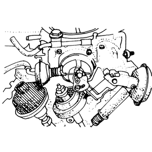
This adjustment should be performed when the throttle body, throttle lock lever
and/or adjusting screw have been tampered with or changed.
- Remove the carburetor from the engine.
- Loosen the locknut and turn the adjusting screw to the left (counterclockwise).
- Close the throttle valve completely and gradually tighten the adjusting
screw until it just touches the throttle lock lever. Tighten the screw an
additional 1⁄8 – 3⁄8 of
a turn, then tighten the locknut.
- Measure the clearance and the angle of opening for the primary throttle
valve when closed. Clearance should be 0.002 in. (0.05mm) and the angle of
opening should be 1 degree. If not, reset the throttle opening with the adjusting
screw.
| Fig. 9: Primary throttle valve adjustment — 1979–80
RX-7
|
- Fully depress the accelerator pedal to make sure the choke valve closes
properly.
- Check for binding in the choke valve by pushing it with your finger.
- Make sure that the bimetal cover index mark is set to the center choke housing
index mark; adjust if necessary.
- Check the automatic choke heater source wiring for proper connection.
- Start the engine and let it idle.
- After the engine warms up, check that the choke valve is fully opened.
- If the valve does not open fully, and the automatic choke heater source
wiring is normal, replace the bimetal cover.
| Fig. 10: The bimetal cover index mark should be set
to the center mark on the choke housing — GLC and
626

|
Perform this check with the engine "overnight'' cold.
- With a cold engine and the ignition switch in the OFF position,
pull the choke knob out fully and make sure the knob returns automatically.
- Connect a tachometer to the engine.
- Start the engine and use the choke knob to set the idle speed to 2,000 rpm.
Allow the engine to run at this speed and observe the temperature gauge. The
choke knob should return back to its original position when the pointer on
the gauge rises to just about the low mid-range portion of the scale.
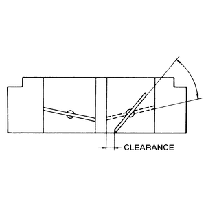
- Close the choke valve fully, then open the primary throttle valve fully.
- Measure the choke valve clearance. The clearance should be 0.08–0.09
in. (2.00–2.40mm) for the GLC and 0.10–0.14 in. (2.65–3.45mm)
for the 626.
- Bend the tab to adjust.
- The secondary throttle valve starts to open when the primary throttle valve
is open 49–51 degrees, and opens completely at the same time that the
primary throttle valve is fully open.
- Check the clearance between the primary throttle valve and the wall of the
throttle bore when the secondary throttle valve starts to open.
- The clearance should be:
- Rear wheel drive GLC hatchback: 0.21–0.26 in. (5.40–6.60mm)
- Rear wheel drive GLC wagon: 0.29–0.32 in. (7.30–8.25mm)
- Front wheel drive GLC — except 1982: 0.21–0.26
in. (5.40–6.60mm); 1982: 0.29–0.33 in. (7.30–8.50mm)
- 626: 0.24–0.28 in. (6.20–7.20mm)
- To adjust the clearance, bend the connecting rod.
| Fig. 11: Secondary throttle valve adjustment — GLC
and 626
|
The throttle sensor should be checked, and adjusted as necessary, whenever
the idle speed has been adjusted.
- Warm up the engine to its normal operating temperature.
- Connect a suitable tachometer to the engine.
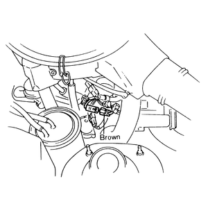
- Detach the brown connector, as illustrated.
| Fig. 12: Unfasten the brown wiring connector
|
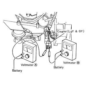
| Fig. 13: When adjusting the RX-7 throttle sensor,
connect a pair of voltmeters as illustrated
|
- Using two voltmeters, connect a negative probe to each terminal (GY and
LgY) of the connector.
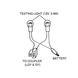
NOTE: A two-bulb test light can be assembled (as illustrated)
and used in place of the voltmeters.
- Connect the positive probe of each voltmeter to the B terminal
of the alternator.
- Start the engine.
- Quickly decelerate the engine speed from 3,000 rpm and check that current
flows to both terminals simultaneously. The engine speed should be 1,000–1,200
rpm.
| Fig. 14: A two-bulb test light can be assembled and
used instead of the voltmeters
|
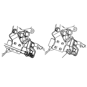
| Fig. 15: After turning the throttle sensor adjusting
screw, reposition its protective cap
|
- If current does not start to flow to both terminals simultaneously, remove
the cap from the throttle sensor adjusting screw.
- Adjust the timing of the current flowing to voltmeter A (connected to LgY)
by turning the throttle sensor adjusting screw. When the screw is turned in
(clockwise), current will begin to flow earlier; when the screw is turned
out (counterclockwise), current will begin to flow later.
- When adjustment is complete, install the cap on the adjusting screw. Remove
the test equipment and fasten the brown connector.
When a rotary engine is hot, the best way to start it is to open the throttle
fully. To save the driver from this task, Mazda has equipped the RX-7 with a
hot start assist motor which opens the throttle while engaging the starter on
a warm engine. The motor is mounted on the left side of the engine compartment
and is attached to the carburetor linkage by a cable. The system can be easily
checked as follows: with the engine warm, open the hood and have an assistant
watch the cable at the hot start assist motor while you engage the starter.
The cable should pull back while the starter is engaged and release as soon
as the starter is disengaged. If the cable requires adjustment, proceed as follows:
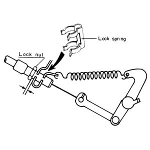
- Remove the lock spring on the cable bracket.
- Slowly pull the outer cable until the hot start lever just touches the stopper
lever. Check the clearance between the cable bracket and the locknut of the
cable. Clearance should be 0.05 in. (1.25mm). Adjust the clearance by turning
the locknut.
- Install the lock spring.
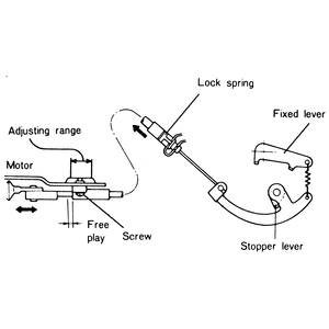
- Pull the start assist motor inner cable until the stopper lever makes contact
with the start lever and check the free-play; it should be 0.04–0.08
in. (1–2mm).
- If the free-play is not as specified, loosen the screw and adjust it.
| Fig. 16: Hot start assist cable adjustment — 1979–83
RX-7
|
| Fig. 17: Hot start assist cable adjustment — 1984–85
RX-7
|

