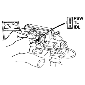
- Install a 0.02 in. (0.5mm) thick gauge between the throttle lever and adjusting
screw. Connect an ohmmeter between the IDL and TL terminals
of the connector. There should be continuity.
- Replace the 0.02 in. (0.5mm) gauge with a 0.03 in. (0.7mm) gauge. Recheck
between the same terminals with the ohmmeter. There should not be continuity.
- If continuity does not disappear with the installation of the thicker gauge
or is not there with the thinner gauge installed, adjust the throttle adjusting
screw so that the throttle sensor passes the test. Reattach the throttle sensor
electrical connector.
- Install a 0.015 in. (0.4mm) thick gauge between the throttle lever and adjusting
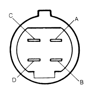
screw. Connect an ohmmeter between the B and D terminals
of the connector. There should be continuity.
- Replace the 0.015 in. (0.4mm) gauge with a 0.022 in. (0.55mm) gauge. Recheck
between the same terminals with the ohmmeter. There should not be continuity.
- If continuity does not disappear with the installation of the thicker gauge,
or is not present with the thinner gauge installed, turn the throttle adjusting
screw so that the throttle sensor passes the test. Reattach the throttle sensor
electrical connector.
| Fig. 1: Connect an ohmmeter between terminals "TL"
and "IDL" to adjust the throttle position sensor — 323

|
| Fig. 2: Connect an ohmmeter between terminals "B"
and "D" to adjust the throttle position sensor — 1986–87
626

|
Throttle sensor adjustment on the 1988–89 626 and MX-6 requires the use
of a special test harness. Adjustment of the throttle sensor on these models
should be performed by a qualified technician.

