Previous Next

Control Panel

REMOVAL & INSTALLATION

323 Models
  1. Remove the screws from the center panel. Do so gently to avoid damaging the panel finish.
  2. Detach the cigarette lighter connector and remove the lamp.
  3. Pull the control panel from the opening in the dash. Note how the control cables are routed. Two cables connect to the heater unit and the third runs to the blower unit. Disconnect the cables from the control panel.

    To install:

  4. Attach the control cables to the control panel.
  5. Adjust the MODE control cable as follows:
    1. Set the mode control knob to the DEF position.
    2. Pull the cable wire downward to its extreme stop. Install the loop of the wire onto the lever.
    3. Pull the connecting rod downward to its extreme stop, then install the connecting rod fastener.
    4. Use the retaining clip to clamp the rod into position.
    5. Position the fan speed at detent number 4 to insure proper air circulation.
    6. Proceed to Step 6 to perform the AIR-MIX door control cable adjustment.
  6. Adjust the AIR-MIX door control cable as follows:
    1. Set the temperature lever to the MAX COLD detent.
    2. Pull the cable lever downward to its extreme stop. Position the cable onto the lever.
    3. Pull the connecting rod lever upward to its extreme stop, then attach the connecting rod to its mounting.
    4. Use the retaining clip to hold the rod in place.
    5. Check for proper operation of the temperature control.
    6. Proceed to Step 7 to perform the REC-FRESH selector cable adjustment.
  7. Adjust the REC-FRESH selector cable as follows:
    1. Position the selector lever in the fresh air intake position.
    2. Push the lever forward to the extreme stop, then attach the cable to the lever.
    3. Check for proper operation of the air selector control.
  8. Install the lamp and fasten the cigarette lighter connector. Gently push the panel into the dash opening and install the retaining screws. Check all the panel control functions for proper operation.
626 and MX-6 With Logic Control
  1. Disconnect the negative battery cable.
  2. Remove the ashtray and radio box from the center console.
  3. Remove the four center panel retaining screws and gently pull the panel outward and away from the dash. Reach in behind the panel and detach the cigarette lighter connector. Remove the center panel.
  4. Remove the two control panel retaining screws and pull the panel out from the console. Unfasten the electrical connectors from the rear of the unit and remove the control panel from the console.

    To install:

  5. Fasten the electrical connectors at the rear of the unit. Push the panel gently into the opening, then install and tighten the retaining screws.
  6. Attach the cigarette lighter connector and hold the center panel against the console. Install and tighten the center panel retaining screws.
  7. Install the radio box and the ashtray.
  8. Connect the negative battery cable.

    Fig. 1: Control head assembly on 626 and MX-6 with Logic Control

626 and MX-6 With Wire Control
  1. Remove the under cover and the glove box.
  2. Disconnect the TEMPERATURE BLEND control cable from the heater unit.
  3. Disconnect the REC-FRESH control cable from the blower case.
  4. On the driver's side, remove the air duct and the under cover.
  5. Disconnect the AIRFLOW MODE cable from the actuating cam on the heater unit.
  6. On 1988–89 models, remove the ashtray and radio box from the center console.
  7. On 1988–89 models, unfasten the stereo cover or center panel retaining screws. Detach the cigarette lighter connector, then remove the cover or panel.
  8. On 1983–87 models, remove the center louver assembly (which frames the control panel).
  9. Remove the two control panel retaining screws and pull the panel out from the instrument panel or console.

    To install:

  10. Push the control panel gently into the instrument panel/console and install the retaining screws.
  11. If applicable, install the center louver assembly.
  12. If applicable, fasten the cigarette lighter connector, then install the stereo cover or center panel.
  13. If applicable, install the radio box and the ashtray.
  14. Adjust the AIRFLOW MODE cable as follows:
    1. Position the mode control cable to the DEF detent.
    2. Connect and clamp the control cable with the shutter lever on the heater unit to the closest point. Move the temperature control lever to be sure that the cable is attached. Be sure it can move from stop to stop without difficulty.
    3. Proceed to Step 15 to perform the TEMPERATURE BLEND cable adjustment.
  15. Adjust the TEMPERATURE BLEND cable as follows:
    1. Position the temperature lever control to the MAX-COLD detent.
    2. Connect the clamp of the control cable to the shutter lever on the right side of the heater unit. Move the temperature control lever to be sure that the cable is attached. Be sure it can move from stop-to-stop without difficulty.
    3. Proceed to Step 16 to perform the REC-FRESH cable adjustment.
  16. Adjust the REC-FRESH cable as follows:
    1. Position the selector lever in the REC detent.
    2. Connect the clamp of the control cable to the shutter lever on the blower unit at its closest point. Move the temperature control lever to be sure that the cable is attached. Be sure it can move from stop-to-stop without difficulty.
  17. Install the driver's side air duct and under cover. Install the glove box and glove box under cover. Connect the negative battery cable and check all the control panel functions for proper operation.

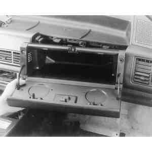
    Fig. 2: Remove the glove box to access the blower unit and cable

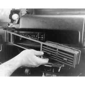
    Fig. 3: Remove the center louver assembly on 1983–87 626 models

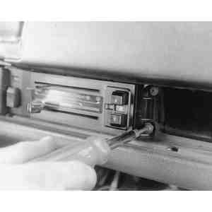
    Fig. 4: Unfasten the screws which retain the control panel

    Fig. 5: AIRFLOW MODE cable adjustment — 626 and MX-6

    Fig. 6: TEMPERATURE BLEND cable adjustment — 626 and MX-6

    Fig. 7: REC-FRESH cable adjustment — 626 and MX-6

Previous Next