Previous Next

Windshield Wiper Motor

REMOVAL & INSTALLATION

1978–82 Models — Except RX-7
  1. Disconnect the negative battery cable.
  2. Unfasten the attaching screws or nuts and remove the wiper arms.
  3. Raise the hood and remove the screws from the front of the cowl plate or from the service hole panel on the firewall. Raise the front of the plate and disconnect the windshield washer hose at the nozzle, then remove the plate.
  4. Disconnect the motor wiring. Unfasten the motor and transmission attaching bolts, then remove the motor and transmission.

    To install:

  5. Position the transmission and motor onto its mounting and install the attaching bolts. Connect the wiring to the motor.
  6. Install the cowl plate and raise it enough to connect the washer hose to the nozzle. Lower the cowl plate and fasten it with the retaining screws.
  7. Install the wiper arms.
  8. Connect the negative battery cable. Check the system for proper operation.
1983 GLC Wagon
  1. Disconnect the negative battery cable.
  2. Unfasten the attaching nuts and remove the two wiper arms.
  3. Unfasten the screws from the front of the cowl grille and remove it.
  4. Mark the relationship between the linkage and motor shaft, then disconnect the linkage at the shaft.
  5. Detach the motor's electrical connector.
  6. Unfasten the three motor mounting bolts (two from the firewall and one from the bracket located directly in front of the windshield) and remove the motor.

    To install:

  7. Installation is the reverse of removal. Make sure the wiper arms are installed so they part in the proper position.
1983–85 GLC Sedan
  1. Disconnect the negative battery cable.
  2. Remove the wiper arms.
  3. Open the hood and remove the driver's side service hole cover from the cowl.
  4. Detach the wiring connector, then unfasten and remove the motor and linkage, as an assembly. If it is necessary to disconnect the crank arm and linkage at the motor, mark their relationship first. This will permit installation in the same position (which is necessary for proper parking).

    To install:

  5. Installation is the reverse of removal.
323 Models
  1. Disconnect the negative battery cable.
  2. Unfasten and remove the access cover from the cowl, adjacent to the wiper motor.
  3. Detach the motor's electrical connector. Remove the three mounting bolts and pull the motor away from the cowl.

    NOTE: Do not disconnect the motor arm unless it absolutely necessary. The relationship of the motor arm to the motor shaft determines the position of the automatic stop angle. If this relationship is disturbed, wiper arm positioning will be affected.

  4. Mark the angle of the linkage drive lever on the motor. Remove the nut and washer, then pry the linkage lever off the motor shaft. Remove the motor.

    To install:

  5. Install the motor in reverse order, with the linkage lever at the same angle. Check the system for proper operation.
1983–87 626
  1. Disconnect the negative battery cable.
  2. Unfasten the attaching nuts and remove the wiper arms.
  3. Pry out the attaching clips from the front of the cowl cover, then remove the cowl cover. Use a screwdriver to release the clips at the rear of the service hole covers.
  4. Remove the two linkage mounting bolts from the cowl area.
  5. Unfasten the motor's electrical connector.
  6. Unfasten the mounting bolts, then remove the motor and linkage assembly.
  7. If the motor and linkage must be separated to replace either, first mark the relationship between the crank arm and linkage, then remove the nut. Use a large screwdriver to pry the linkage off the crank arm.

    To install:

  8. If the linkage and crank arm were separated, press the linkage onto the arm, making sure to observe the original relationship described in Step 7.
  9. Position the motor and linkage onto its mounting, then install the mounting bolts.
  10. Fasten the electrical connector.
  11. Install the two linkage bolts in the cowl.
  12. Install the service hole covers and the cowl cover.
  13. Install the wiper arms and properly tighten the attaching nuts.
  14. Connect the negative battery cable and check the system for proper operation.

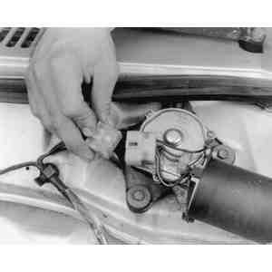
    Fig. 1: Unfasten the electrical connector from the wiper motor

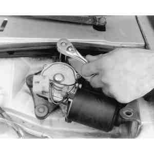
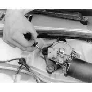
    Fig. 2: Use a wrench to unfasten . . .

    Fig. 3: . . . and remove the motor's mounting bolts

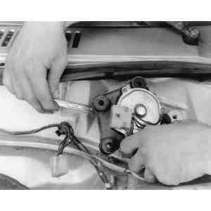
    Fig. 4: If necessary, remove the nut which retains the linkage to the wiper motor . . .

    Fig. 5: . . . then remove the wiper motor from the vehicle

    Fig. 6: Proper installation angle for wiper linkage on the 1983–87 626

1988–89 626 and MX-6
  1. Disconnect the negative battery cable.
  2. Remove the wiper blade and arm assemblies.
  3. Unfasten the attaching screws and remove the lower molding.
  4. Unfasten and remove the two lower cover pieces from the left and right sides of the vehicle.
  5. Disconnect the wiper linkage from the wiper motor shaft. DO NOT disconnect the motor arm unless it is absolutely necessary. The relationship of the motor arm to the motor shaft determines the position of the automatic stop angle. If this relationship is disturbed, wiper arm positioning will be affected.
  6. Detach the wiper motor connector. Unfasten the attaching bolts and remove the wiper motor.

    To install:

  7. Position the motor onto its mounting and install the attaching bolts. Connect the wiring to the motor.
  8. Connect the wiper linkage to the motor shaft and tighten the nut.
  9. Attach the left and right lower covers, then install the lower molding.
  10. Install the wiper arm/blade assemblies.

    NOTE: The wiper arm/blade assemblies are identified by letters on the portion of the blade that connects to the wiper linkage. The driver's side arm is marked "DL'' and the passenger's side is marked "PL''. Make sure that the wiper arms are installed in their original positions, as they are not interchangeable.

  11. Connect the negative battery cable. Check the wiper system for proper operation.
929 Models
  1. Disconnect the negative battery cable.
  2. Remove the wiper arms.
  3. Unfasten the attaching screws and remove the lower front window molding.
  4. Detach the wiper motor electrical connector, then unfasten and separate the linkage assembly from the wiper motor.
  5. Unfasten the mounting bolts and remove the wiper motor from the vehicle.

    To install:

  6. Align the tang in the motor shaft with the slot in the linkage. When properly aligned, engage the motor shaft and linkage, then install the wiper motor attaching bolts.
  7. Fasten the wiper motor electrical connector and install the lower front window molding.
  8. Install the wiper arms by placing the blade on top of the wiper stopper and tightening the locknut to 7–11 ft. lbs. (9.5–15 Nm). After the nuts are tightened, move the wiper blades down to the stop position.
  9. Connect the negative battery cable and check the wiper system for proper operation.

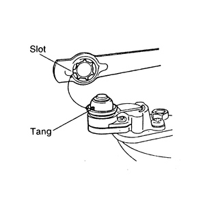
    Fig. 7: Wiper motor and linkage alignment — 929

1979–85 RX-7
  1. Turn the ignition switch ON. Activate and stop the windshield wipers, so that the wiper blades are positioned at the center of the windshield, by disconnecting the negative battery cable.
  2. Remove the wiper arms.
  3. Remove the seal caps, then unfasten the nuts on the wiper linkage shafts.
  4. Remove the cup washers and outer bushings.
  5. Unfasten the cowl plate attaching screws and remove the cowl plate.
  6. Disconnect the washer hose at the washer nozzle.
  7. Detach the wiper motor electrical connections and unfasten the mounting bolts.
  8. Remove the wiper motor and linkage assembly as a unit.
  9. Installation is the reverse of the removal procedure.
1986–89 RX-7
  1. Disconnect the negative battery cable.
  2. Disengage the wiper arms from the linkage shafts.
  3. Unfasten the attaching screws and remove the cowl grille.
  4. Disconnect the wiper link from the motor arm. DO NOT disconnect the motor arm unless it is absolutely necessary. The relationship of the motor arm to the motor shaft determines the position of the automatic stop angle. If this relationship is disturbed, wiper arm positioning will be affected.
  5. Detach the wiper motor connector. Unfasten the motor attaching bolts and remove the wiper motor.

    To install:

  6. Position the wiper motor onto its mounting, then install and tighten the bolts. Attach the wiper motor connector.
  7. Install the cowl grille and the wiper arms.

    NOTE: The wiper arm/blade assemblies are identified by letters on the portion of the blade that connects to the wiper linkage. The driver's side arm is marked "DL'' and the passenger's side is marked "PL''. Make sure that the wiper arms are installed in their original positions. They are not interchangeable.

  8. Connect the negative battery cable and check the wiper system for proper operation.

Previous Next