Previous Next

CV-JOINT OVERHAUL

GLC

NOTE: The joint on the wheel side of the drive axle is non-rebuildable. If worn, the joint and axle must be replaced. However, the boot may be changed as necessary. Do not interfere with the balancer found on the right shaft unless necessary for wheel joint boot replacement. If the balancer is removed, it must be reinstalled in the same position (14.45 in. or 367mm from the front of the wheel joint).

  1. Remove the boot band by raising the locking clip and band with a pair of pliers.
  2. Remove the lock clip from the inner edge of the ball joint casting. Remove the casting.
  3. Remove the snapring from the end of the splines, then remove the cage and bearings.
  4. Carefully pry the balls from the bearing cage. After the balls are removed, turn the cage slightly and remove it from the inner ring.
  5. Wash all of the parts in a safe solvent and inspect for wear.

    NOTE: CV-joint overhaul parts are available in kits for serviceable (inner) joints. Replacement boots should be available for all outer ends.

  6. Install the replacement parts in the reverse order of disassembly. Always use the grease supplied with the kits. Tape the spline ends of the shaft when installing the rubber boots.
323, 626 and MX-6
  1. Disassemble the driveshaft (halfshaft) as shown in the exploded view. The clip (2) should be removed with a small prytool, while the snapring (4) should be removed with snapring pliers or a similar tool.
  2. Pull the ball bearings, inner ring and cage out of the shaft while still assembled. Insert an small prytool between the inner ring and cage to gently pry each ball out. Matchmark the cage and inner ring, then turn the cage 30 degrees and pull it off the inner ring.
  3. Assemble in the reverse order, being careful to thoroughly repack bearings in the grease supplied with the kit.

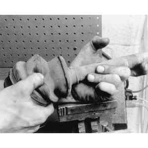
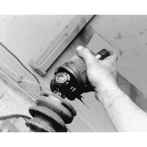
    Fig. 1: Check the CV-boot for wear or damage

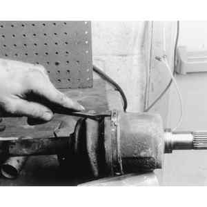
    Fig. 2: Release (or cut) the outer band from the CV-boot

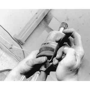
    Fig. 3: Use cutters to carefully release the inner band from the CV-boot

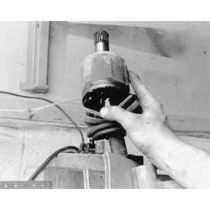
    Fig. 4: Remove the CV-boot from the joint housing

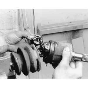
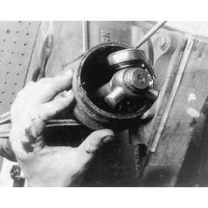
    Fig. 5: Remove the CV-joint housing assembly to access the joint components

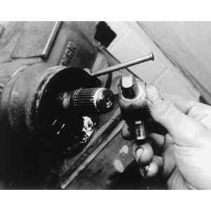
    Fig. 6: Carefully remove the CV-joint components

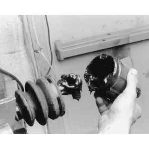
    Fig. 7: Thoroughly clean and inspect the CV-joint housing

    Fig. 8: Remove the CV-joint outer snapring

    Fig. 9: Remove the CV-joint assembly

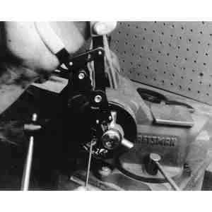
    Fig. 10: Use a pair of snapring pliers to remove the CV-joint inner snapring

    Fig. 11: Installing the CV-joint assembly

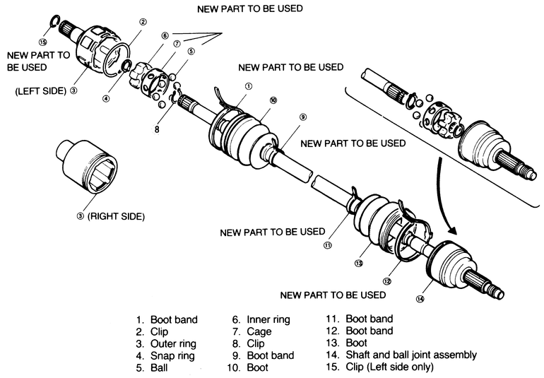
    Fig. 12: Exploded view of 626 driveshaft and CV-joint; 323 and MX-6 similar

Previous Next