
- Raise the rear end of the car and support it using jackstands.
CAUTION
Be sure that the car is securely supported. Remember, you will be working
underneath it.
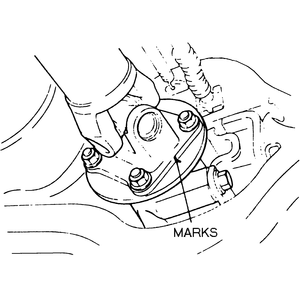
- Matchmark the flanges on the driveshaft and pinion so that they may be installed
in their original position.
| Fig. 1: Matchmark the driveshaft flanges before removing
the driveshaft

|
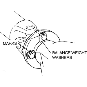
| Fig. 2: If so equipped, be sure to also matchmark
the balance washers

|
- Remove the four bolts which secure the driveshaft to the pinion flange.
- Lower the back end of the driveshaft and slide the front end out of the
transmission.
- Plug up the hole in the transmission to prevent it from leaking.
NOTE: Use an old U-joint yoke or, if none is available,
place a plastic bag secured with rubber bands over the hole.
- To install, slide the front end of the driveshaft into the transmission
and raise the rear end of the shaft onto the pinion flange making sure that
the matchmarks are aligned properly. Install the flange bolts and torque to
25–27 ft. lbs. (34–37 Nm).
- Lower the vehicle.
The driveshaft used on 626 models is removed in a manner similar to that outlined
for GLC models. The only difference in the removal procedure is that the center
bearing must be unbolted prior to driveshaft removal. Remove the driveshaft
and the center bearing as a single unit.
NOTE: Do not remove the oil seals and the center bearing from
the support unless they are defective.
Installation is performed in the reverse order of removal. Tighten the center
bearing support bolts to 27–38 ft. lbs. (37–51 Nm) for the 626 and
the driveshaft-to-pinion flange bolts to 25–27 ft. lbs. (34–37 Nm).
- Raise the rear end of the car and support it using jackstands.
CAUTION
Be sure that the car is securely supported. Remember, you will be working
underneath it.
- Matchmark the flanges on the driveshaft and pinion so that they may be installed
in their original position.
- Remove the four bolts which secure the driveshaft to the pinion flange.
- Remove the bolts, washers, bushings and spacers that secure the center bearing
support bracket.
- Lower the back end of the driveshaft and slide the front end out of the
transmission.
NOTE: Transmission fluid may flow out of the rear of the
transmission when the yoke is removed, so either use the turning holder
(tool number 49 S120 440) or a used driveshaft yoke to plug the transmission.
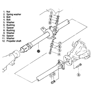
| Fig. 3: Exploded view of driveshaft assembly — 929

|
To install:
- Slide the front end of the driveshaft into the transmission and raise the
rear end of the shaft onto the pinion flange, making sure that the matchmarks
are aligned properly.
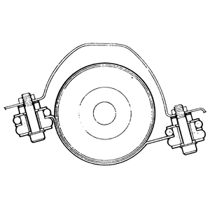
| Fig. 4: Driveshaft alignment — 929

|
- Torque the flange bolts to 36–43 ft. lbs. (49–58 Nm).
- Using the exploded view as a guide, assemble the washers, bushings and spacers
onto the support bracket bolts, then install the bracket onto center bearing.
Torque the bracket bolts to 27–38 ft. lbs. (37–51 Nm).
- Check the front and rear driveshafts for proper alignment (see illustration)
after the center bearing support is in place and torqued down. If the shafts
are not aligned as shown, adjust the height of the center bearing support
bracket with shims and bolts which may be purchased at your local Mazda dealer.
- Raise the rear of the car and support it on jackstands.
- Matchmark the position of the rear driveshaft, pinion yokes and balance
washers so that the driveshaft will be installed in the same position and
to avoid the possibility of vibration problems.
- Remove the four attaching bolts at the rear of the driveshaft, and remove
the driveshaft toward the rear of the vehicle, sliding it out of the back
of the transmission.
NOTE: Transmission fluid may flow out of the rear of the
transmission when the yoke is removed, so insert use the turning holder
(tool number 49-0259-440) into the rear of the housing or a used driveshaft
yoke to lug the transmission.
- Install the driveshaft in the reverse order of removal. Be careful not to
damage the rear transmission seal when installing the driveshaft on the splined
shaft in the transmission. Make sure you align the matchmarks made earlier
on the driveshaft yokes and balance washers. The yokes on the driveshaft and
the rear axle must be aligned as they were when removed or the driveshaft
may be out of balance and cause vibration. Tighten the bolts to 25–27
ft. lbs. (34–37 Nm) on 1979–85 models and 36–43 ft. lbs.
(49–58 Nm) on 1986–89 models.
If a new driveshaft was installed and the vehicle is experiencing vibration
problems, the driveshaft may have to be balanced. Balancing is performed
by placing weights on the flange bolts at different locations on the flange.
The balance weights are available in 0.12 oz. (3.4 g) and 0.20 oz. (5.7
g) sizes from your local Mazda dealer.


