

- Raise and support the vehicle safely. Remove both front wheels and splash
shields. Drain the transaxle fluid.
- Loosen the drive axle locknut at the center of the disc brake hub after
raising the lock tab. Apply brake pressure while loosening.
- Remove the lower ball joint from the steering knuckle by pulling down on
the bar and disconnecting the ball joint.
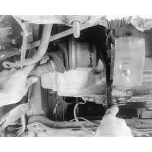
- Remove the axle shaft from the transaxle case by pulling the brake caliper
outward with increasing force. While applying outward force, hit the driveaxle
shaft with a brass hammer, if necessary, to help in removal. Beware, if the
shaft is withdrawn too fast you may risk damaging the oil seal.
- Remove the locknut and pull the axle shaft from the steering knuckle. Remove
the axle shaft and plug the transaxle case with a clean rag to prevent dirt
from entering. Discard the axle shaft locknuts and purchase new ones.
To install:
- Before installing the axle shaft into the transaxle case, check the oil
seals for cuts or damage. Replace the oil seals if necessary. Replace the
circlips on the splined ends of the shaft. Coat the oil lip with clean ATF
fluid and grease the lip of the wheel hub oil seal.
- Insert the axle into the transaxle case by pushing on the wheel hub assembly.
Pull the caliper and wheel hub assembly outward, then insert the driveshaft
into the wheel hub. Temporarily install the locknut onto the end of the shaft
to hold the shaft in place.
- Have an assistant apply the brakes and torque the axle locknut to 116–174
ft. lbs. (157–236 Nm). Stake the tab of the locknut so that at least
0.016 in. (4mm) of the tab is protruding above the groove. Use a small cold
chisel to stake the tab, do not use a pointed tool.
- Install splash shields and the front wheels. Lower the vehicle. Fill the
transaxle to the proper level.
NOTE: On 1988–89 626s and MX-6s, removal and installation
of halfshafts is the same for manual and automatic transaxles. On 323s with
4wd, refer to the REAR AXLE portion of this section for rear halfshaft removal
and installation.
- Raise the vehicle and support it on axle stands. Drain the lubricant from
the transaxle.
- Remove the front wheels and splash pan. Raise the tab on the wheel hub locknut,
and then have someone apply the brakes as you loosen the nut.
- Remove the tow nuts, bushings, and washers, then disconnect the stabilizer
bar from the steering knuckle.
- Remove the clinch bolts and nuts, then pry the lower control arm downward
in order to separate the steering knuckle and lower ball joint. Be careful
not to damage the ball joint dust cover.
On the left side:
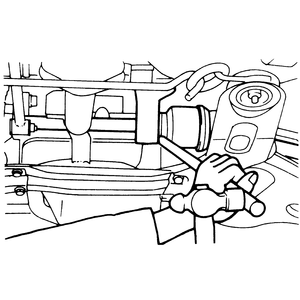
- Insert a lever (for automatic transaxles, you'll have to use a chisel) between
the driveshaft and transaxle case (don't go in too for, or you will damage
the seal). Tap the end of the pry bar or chisel lightly to pull the shaft
out of the case just until it unlocks.
| Fig. 1: Insert a lever between the left-side driveshaft
and transaxle case
|
| Fig. 2: Pull the front hub outward and separate the
driveshaft from the transaxle
|
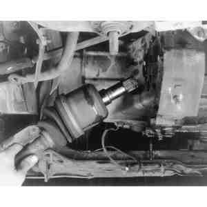
- Remove the driveshaft locknut from the center of the brake rotor. Pull the
front hub outward and toward the rear. Disconnect the driveshaft from the
wheel hub. If necessary, use a puller. Then, pull the driveshaft straight
out of the transaxle, supporting the joint on the transaxle side to prevent
damage to the seal. Seal the transaxle opening with a clean rag.
On the right side:
- Insert a lever between the joint shaft and driveshaft, then gently tap on
the outer end of the lever to separate the two shafts.
| Fig. 3: Levering the joint shaft and right-side driveshaft
apart on the 626
|
- Remove the driveshaft locknut, then pull the front hub outward and toward
the rear. Disconnect the driveshaft from the front hub. If necessary, use
a puller. Then, disconnect the driveshaft from the cross-shaft completely.
- If it is necessary to remove the cross-shaft, remove the cross-shaft mounting
bracket bolts, then remove the shaft and bracket as an assembly, being careful
not to disturb the position of differential gears. Cover the opening in the
differential case with a clean rag.
- Installation is the reverse of removal, but note these points:
- Check the transaxle oil seal for damage and replace it if necessary.
- Replace the clips at the inner ends of the driveshaft or cross-shaft
where they are locked into the differential gears in the transaxle.
- Install the shafts into the transaxle carefully to avoid damage to the
oil seal. Push the joint in on the differential side. Check the differential
gears for alignment before attempting to install the shafts. If they are
not aligned, turn them with your finger, as necessary.
- After installation, pull the hub forward to make sure the driveshaft
remains locked in the transaxle.
- Install a new locknut onto the outer end of the driveshaft, adjusting
wheel bearings as described in section 8. Crimp the tabs over after they
are aligned with the groove in the driveshaft.
- Tighten the stabilizer bar link nut until 1 in. (25mm) of thread is
exposed.
- Torque the lower control arm-to-ball joint nut and bolt to 32–40
ft. lbs. (43–54 Nm).
- Torque the control link for the lower arm and stabilizer bar to 9–13
ft. lbs. (12–18 Nm); except for the 1988–89 626s and MX-6s
on which it should be 12–17 ft. lbs. (16–23 Nm).
- Refill the differential with fresh fluid meeting proper specifications.