NOTE: The left and the right rear axle shafts are not interchangeable,
as the left shaft is shorter than the right. It is, therefore, not a good idea
to remove them both at once.
- Remove the wheel cover and loosen the lug nuts.
- Raise the rear of the car and support the axle housing on jackstands.
- Unfasten the lug nuts and remove the wheel.
- Remove the brake assembly. (See Section 9.)
- Unfasten the nuts which secure the brake backing plate and the bearing retainer
to the axle housing.
- Withdraw the axle shaft with a puller.
To install:
- Apply grease to the oil seal lips and then insert the oil seal into the
axle housing.
- On all models but GLC check the axle shaft end-play in the following manner:
- Temporarily install the brake backing plate on the axle shaft.
- Measure the depth of the bearing seal and then measure the width of
the bearing outer race.
- The difference between the two measurements is equal to the overall
thickness of the adjusting shims required. Shims are available in thicknesses
of 0.004 in. (0.1mm) and 0.016 in. (0.4mm).
NOTE: The maximum permissible end-play is 0.004 (0.1mm).
- Remove the backing plate and apply sealer to the rear axle surfaces which
contact it. Install the backing plate again.
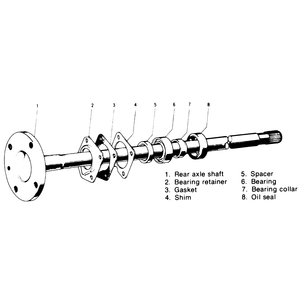
- Install the rear axle shaft, bearing retainer, gasket, and shims through
the backing plate and into the axle housing. Coat the shims with a small amount
of sealer first.
- Engage the splines on the differential side gear with those on the end of
the axle shaft.
- Install the wheel and lower the car.
| Fig. 1: Components of the rear axle shaft assembly
|
- Raise and safely support the rear of the vehicle. Drain the lubricant from
the differential.
- Remove the rear wheels. Raise the tab on the wheel hub locknut, and then
have someone apply the brakes as you loosen the nut.
- Clearly mark the relationship between the driveshaft flange and the differential.
Remove the nuts and washers that attach the driveshaft to the differential
and separate them.
- Disconnect the lateral link from the rear axle hub by removing the through-bolt
and washer. Disconnect the trailing link in the same manner.
- Lower the driveshaft flange from the differential and pull the splined end
from the wheel hub. If the driveshaft is stuck in the hub, use special hub
puller 49-0839-425C or equivalent to withdraw the hub so you can remove the
driveshaft.
- Unbolt and remove the rear axle assembly from the shock absorber support.
To replace the bearings and oil seals:
- Press the wheel hub and disc plate from the knuckle using an arbor press
and special attachments 49-B026-102, 49-G033-102 and 49-G030-727 or their
equivalents. Support the wheel hub and disc plate to keep it from falling.
- Matchmark the wheel hub and the disc plate, then remove wheel hub.
- Support the wheel hub on V-blocks with the bolts facing down. Place special
tool 49-0636-145 or equivalent between the oil seal and the hub. Press the
outer bearing and oil seal from the hub. Save the spacer.
- Pry the inner oil seal from the wheel hub with a small prytool, then drive
the inner and outer bearing races out of the hub using a brass drift punch
and a hammer.
- Install the new inner and outer bearing races, then seat them in the knuckle
by tapping alternately and evenly using the brass drift and hammer.
- Install the inner bearing, original spacer and outer bearing, then place
special preload adjustment tool 49-B001-727 or equivalent on top of the outer
bearing. Torque the special tool to 17 inch lbs (2 Nm). Mount the knuckle
in a protected jaw vise so that the jaws are clamped on the wheel hub shaft.
Hook a spring scale to the knuckle and measure the preload. The correct preload
is 1.74–6.94 inch lbs (0.2–0.8 Nm). If not as specified, adjust
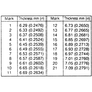
the preload by selecting the appropriate spacer from the accompanying chart.
If the bearing preload is greater than the specified amount, select a thicker
spacer. If the bearing preload is less than the specified amount, select a
thinner spacer. If the preload is within the specified value, use the old
spacer.
| Fig. 2: Spacer selection chart — 323
with 4wd
|
NOTE: Although Mazda recommends packing the bearings after
installation (with the seals driven into position), you may wish to pack
them before installation to assure proper greasing. If you decide to grease
the bearings before installation, just make sure that the preload measurements/adjustments
have already been performed as the grease would adversely affect your measurements.
- Install the inner bearing into the knuckle. Coat the lip of the inner oil
seal with a good quality lithium based grease and install the seal using special
seal installer tool 49-B001-795 or equivalent. A piece of pipe or socket that
closely approximates the diameter of the seal may be substituted for this
tool. Install the outer bearing and outer oil seal in the same manner as the
inner. If not done already, pack the inner and outer bearings with lithium
based grease.
- Place the disc plate onto the wheel hub so that the matchmarks are aligned
and install the wheel hub retaining bolts. Torque the bolts to 33–40
ft. lbs. (45–54 Nm).
- Press the hub into the knuckle.
To install:
- Attach the knuckle assembly to the shock absorber support and torque the
retaining bolts to 58–86 ft. lbs. (79–117 Nm).
- Insert the splined end of the driveshaft into the wheel hub, then connect
the trailing and lateral links. Torque the trailing link bolt to 69–86
ft. lbs. (93–117) and the lateral link bolt to 46–55 ft. lbs.
(62–75).
- Attach the driveshaft flange to the differential by aligning the matchmarks.
Torque the flange nuts to 36–43 ft. lbs. (49–58 Nm).
- Install a new locknut and torque it to 116–174 ft. lbs. (157–236
Nm) Stake the locknut tab into the groove of the spindle using a small cold
chisel.
- Install the rear wheels and lower the vehicle.
- Raise and safely support the rear of the vehicle.
- Remove the rear wheels and uncrimp the tab on the rear axle nut with a small
cold chisel. Have an assistant apply the brakes and loosen the rear axle nut
and washer. Discard the nut and washer as they must be replaced with new ones.
- Mark the relationship of the driveshaft flange to the differential and unbolt
the driveshaft. Lower the driveshaft flange and withdraw the splined end from
the axle.
- Remove the caliper and support the assembly with a piece of rope or wire
to relieve the stress on the brake line. Leave the brake line connected.
- Remove the retaining screws and pull the rotor disc from the wheel hub.
- Remove the parking brake shoe assembly (see Section 9) and disconnect the
parking brake cable by loosening the dust cover bolts. If equipped with ABS,
disconnect and remove the wheel speed sensor from the rear hub support. Position
the sensor off to the side and out of the way.
- Disconnect the trailing arm, shock absorber, stabilizer control link, upper
control link and lower control links (front and rear).
- Unfasten the bolts and remove the rear axle/hub support assembly.
To replace the oil seal and bearing:
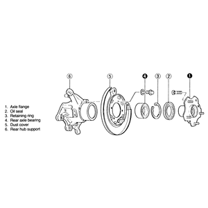
- Place the bearing support hub in special support fixture 49-HO26-108 or
equivalent and press the axle flange from the hub. Look at the axle flange
after it is freed from the hub. If the bearing inner race is still attached
to the flange, use a grinding wheel to remove the race metal until only 0.02
in. (0.5mm) remains, then remove the rest with a cold chisel.
- Remove the oil seal hub. With snapring pliers, remove the bearing retaining
ring and press the bearing from the hub spindle. Purchase a new oil seal and
bearing.
- Press a new bearing into the hub and replace the snapring. Coat the lip
of the new oil seal with multi-purpose grease and install the seal into the
hub.
| Fig. 3: Exploded view of rear axle and hub assembly — 929
|
- Press the axle flange into the hub using special installer tools 49-F026-102
and 49-H026-104 or equivalent.
To install:
- Support the axle by hand and connect the rear lower link to the wheel side.
Torque the fastener to 40–55 ft. lbs. (54–75 Nm). Connect and
tighten the front lower link in the same manner. The body side bolts will
be torqued later.
- Connect the upper link (wheel side) to the hub support and torque the retaining
bolt to 40–55 ft. lbs. (54–75 Nm). The body side bolts will be
torqued later.
- Install the hub support bolts and torque them to 69–86 ft. lbs. (93–117).
Connect the upper control link, stabilizer control link, shock absorber and
trailing arm.
- Install the wheel speed sensor and torque the retaining bolt to 12–17
ft. lbs. (16–23 Nm). Loosen the dust cover bolts to gain installation
clearance for the parking brake cable. Install the parking brake cable and
torque the dust cover bolts to 40–50 ft. lbs. (54–68 Nm) and the
cable bolts to 34–39 ft. lbs. (46–53 Nm).
- Install the parking brake shoe assembly and place the rotor disc onto the
axle hub. Secure the disc with the retaining screws.
- Install the caliper assembly and torque the caliper bolts to 33–50
ft. lbs. (45–68 Nm).
- Insert the splined end of the driveshaft into the hub and raise the driveshaft
flange so that the matchmarks on the flange and differential are aligned.
Install the flange bolts and torque them to 40–47 ft. lbs. (54–64
Nm).
- Install the new washer and axle nut. Have an assistant apply the brakes
and torque the nut to 174–231 ft. lbs. (236–313 Nm). Stake the
tab of the locknut with a small cold chisel so that at least 0.16 in. (4mm)
protrudes above the spindle groove.
- Install the rear wheels and lower the vehicle. Bounce the rear of the vehicle
several times to seat the suspension. Torque the body side lower link front
bolts to 69–86 ft. lbs. (93–117) and the rear bolts to 54–86
ft. lbs. (73–117 Nm). Torque the body side upper link bolts to 69–86
ft. lbs. (93–117). Torque the stabilizer link bolts to 27–38 ft.
lbs. (37–51 Nm). Torque the shock absorber bolts to 54–69 ft.
lbs. (73–93 Nm).
- Have the rear toe-in adjusted.
- Loosen, but do not remove, the rear wheel lug bolts.
- Raise the vehicle and safely support it on jackstands. Remove the wheels.
- Remove the brake drum and shoes or the disc brake caliper and disc as instructed
in Section 9.
- Disconnect the four bolts attaching the brake backing plate to the axle
housing.
- Disconnect the parking brake cable clip and remove the cable. Disconnect
any interfering brake lines attached to the backing plate.
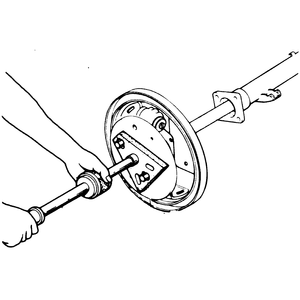
- Remove the axle shaft/backing plate assembly by attaching a slide hammer
to the axle shaft.
| Fig. 4: Removing the axle shaft and brake backing
plate with a slide hammer — 1979–85 RX-7
|
- Remove the inner oil seal by prying it out.
NOTE: Remove the inner oil seal only if it is defective,
because the seal will probably be damaged when removed.
To replace the bearing:
- The wheel bearing can be pressed off the axle shaft using bearing separator
(tool number 49 8531 746 or equivalent) and its attachment (tool number 49
0259 747 or equivalent). Assemble the separator and attachment as shown in
the illustration.
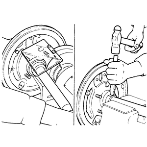
- If the separator and its attachment are not available, or if the press does
not generate enough force to press off both the bearing and its retaining
collar, grind the bearing retaining collar down, then cut it with a chisel
to loosen its grip. Remove the collar.
CAUTION
Be sure to use safety glasses and be careful not to damage the axle shaft
itself with the chisel.
| Fig. 5: If necessary, the collar can be removed with
a hammer and chisel
|
- Remove the bearing with a puller or a press. Remove the spacer and backing
plate.
- Install the backing plate and spacer on the axle shaft with the chamfer
of the spacer toward the axle shaft flange.
- Position the bearing on the axle shaft and press it until the spacer comes
in contact with the shoulder on the shaft.
- Clean off the new bearing retaining collar and its mounting space on the
axles shaft, then press the bearing retaining collar on the shaft until it
firmly contacts the bearing inner race.
NOTE: Never lubricate the retaining collar when installing.
Always use a new bearing retaining collar. If the bearing retaining collar
can be press fit using less than 2.7 tons (5,900 lbs.) of pressure, replace
the collar with a tighter fitting one.
To install:
- If removed, lubricate and install the new oil seal in the axle shaft housing.
Apply grease to the oil seal lip.
- Install the axle shaft in the reverse order of removal, being careful not
to damage the oil seal with the splined end of the shaft. Engage the splines
on the shaft with the splines in the rear axle.
- Loosen the rear wheel lug nuts. Raise and safely support the rear of the
vehicle.
- Remove the rear wheels. Raise the tab on the wheel hub locknut, and then
have someone apply the brakes as you loosen the nut.
- Remove the caliper and support the assembly with a piece of rope or wire
to relieve the stress on the brake line. Leave the brake line connected.
- Remove the retaining screws and pull the rotor disc from the wheel hub.
On vehicles equipped with ABS, remove the speed sensor probe from the knuckle.
Move the probe off to the side and out of the way.
- Unbolt and pull the rear knuckle assembly from the driveshaft.
To replace the bearing:
- Remove the dust cover. The wheel hub can now be pressed from the toe control
hub using bearing installer tool 49-F026-102 or equivalent and wheel hub puller
49-F026-103 or equivalent.
- Install fan pulley boss puller 49-0636-145 or equivalent onto the hub and
press the inner race from the hub using bearing installer tool 49-F026-102
or equivalent.
- Remove the snapring from the bore of the toe control hub and press the bearing
outer race from the hub using attachment 49-F027-007 or equivalent.
- Press the new bearing and race assembly into the toe control hub using bearing
installer tool 49-F026-102 or equivalent and bearing separator attachment
49-0259-748 or equivalent.
- Install a new snapring and install the dust cover.
- Press the hub onto the knuckle using the installer tool described in Step
9.
To install:
- Mount the hub onto the driveshaft and the rear axle casing. Torque the knuckle
bolts to 46–69 ft. lbs. (62–93 Nm) and the driveshaft bolts to
82–111 ft. lbs. (111–150 Nm).
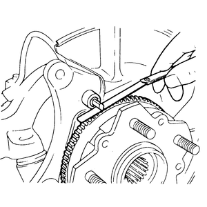
- Install the disc plate and caliper assemblies. If equipped with ABS, insert
the speed sensor probe into the knuckle. The tip of the probe must be aligned
with the edge of the rotor. Check the clearance between the sensor and the
sensor rotor with a feeler gauge. The clearance should be 0.016–0.04
in. (0.4–1.0mm).
| Fig. 6: Checking the clearance between the speed
sensor and rotor — 1986–89 RX-7
|
- Install a new axle nut. Have an assistant depress the brake pedal and torque
the nut to 174–231 ft. lbs. (236–313 Nm). Crimp the nut to the
spindle groove with a small cold chisel.
- Mount the rear wheels and lower the vehicle.


