NOTE: A circlip is positioned on the driveshaft ends and engages in a groove, machined in the differential side gears. The driveshafts may have to be forced from the differential housing to release the clip from the groove. Do not apply a sharp impact. Do not allow the driveshaft's free end to drop, otherwise may occur to the ball and socket joints as well as to the rubber boots. Wire the shafts to the vehicle body when released from the differential.
To install:
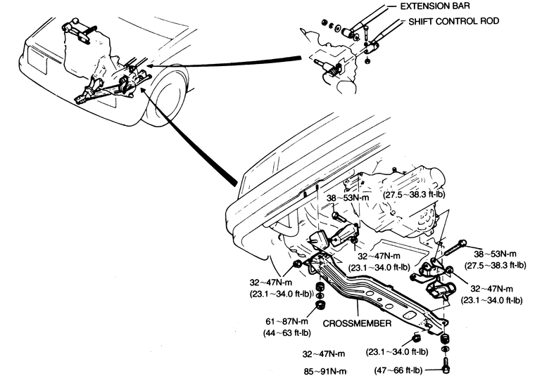
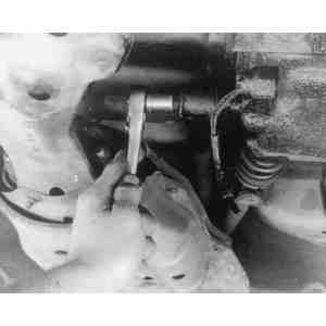
| Fig. 1: Disconnecting shift linkage and removing
the crossmember — GLC manual transaxle
|
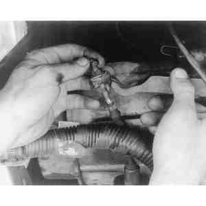
| Fig. 2: Loosen the nuts which secure the clutch cable
to the release lever . . .
|
| Fig. 3: . . . then disengage the cable from the lever
|
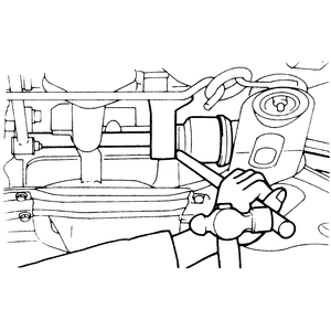
| Fig. 4: Removing the left-side driveshaft from the
626 transaxle
|
| Fig. 5: Removing the right-side driveshaft from the
626 transaxle
|
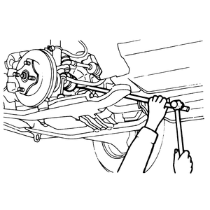
| Fig. 6: Disconnect the locating rod at the transaxle
|
To install:
Observe the following torque figures:
NOTE: Do not insert the lever too deeply between the shaft and the case or the oil seal lip could be damaged. To avoid damage to the oil seal, hold the CV-joint at the differential with one hand and pull the driveshaft straight out.
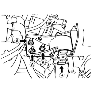
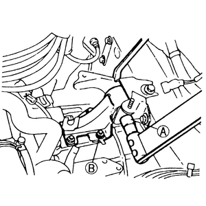
| Fig. 7: No. 4 transaxle mount — 1988–89
626 and MX-6
|
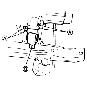
| Fig. 8: No. 2 transaxle mount — 1988–89
626 and MX-6
|
To install:
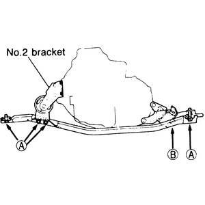
| Fig. 9: Crossmember mounting and brackets — 323
with 2wd
|
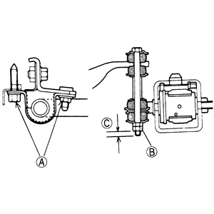
To install:
| Fig. 10: 323 stabilizer bar adjustment
|
| Fig. 11: No. 4 mounting bracket — 323
with 4wd
|
To install: